Device and Functional Specifications
MicroPeckerX Device Specifications S810-MX-FD2
| Item | Description |
|---|---|
| Power supply | USB Bus Power (5V, 300mA) |
| Dimensions | 65(W) x 35(D) x 16(H) mm |
| Weight | 45 g |
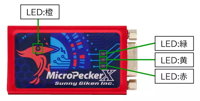
| LED | 4 LEDs installed: Orange: Power status (ON when powered) Green: Communication Ch1 (blinks during CAN/CAN FD communication on Ch1*) Yellow: Communication Ch2 (blinks during CAN/CAN FD communication on Ch2*) Red: Error (ON when abnormality occurs) *Blinks on reception/transmission of GW target IDs and periodic transmission, excluding immediate GW Tx/Rx. |
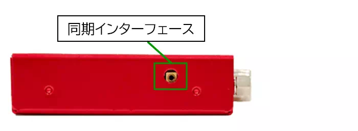
| Synchronization interface | 2 ports |
| CAN/CAN FD interface | D-Sub 9-pin, 2 channels |
| USB ports | Two USB Micro-B ports (Main, Sub) |
International Standards
- CE marking acquired
EMI: EN55011(2020) Group1 ClassB
EMS: EN61000-4-2(2009), EN61000-4-3(2010) - FCC compliant
This device complies with Part 15 of the FCC Rules. Operation is subject to the following two conditions:
(1) This device may not cause harmful interference, and (2) This device must accept any interference received, including interference that may cause undesired operation.
Front
Top/Bottom Side
Left/Right Side
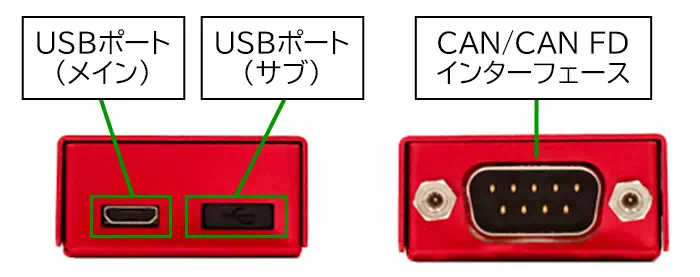
Note: Do not use the USB Sub port.
CAN 1ch Clip Cable Specifications S810-MX-CB1
| Item | Description |
|---|---|
| Signal | CAN-Hi, CAN-Lo, GND (clip connector) |
| Cable length | Total length: 0.3 m |
| Shield | None |
Connector pinout

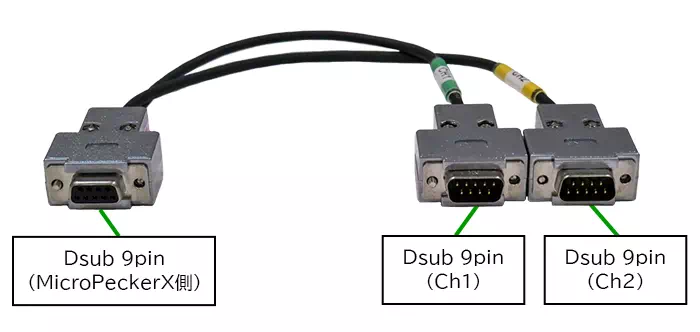
CAN 2ch D-Sub Cable Specifications S810-MX-CB2
| Item | Description |
|---|---|
| Signal | CAN-Hi, CAN-Lo, GND (D-Sub 9-pin connector) |
| Cable length | Total length: 0.3 m |
| Shield | Available |
Connector pinout
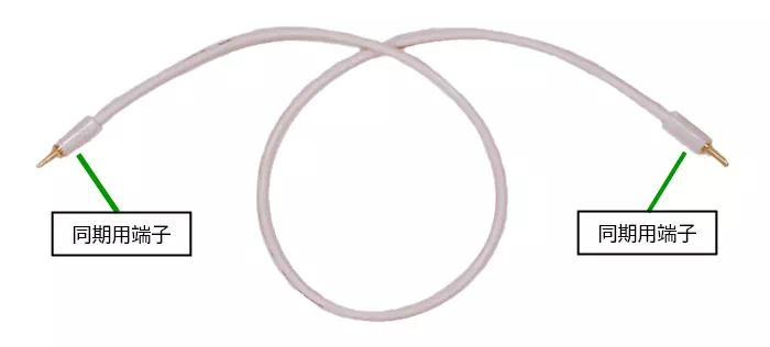
Synchronization cable specifications
| Item | Description |
|---|---|
| Cable length | Total length: 25 cm |
| Shield | None |
Note: Synchronization cable is not used in this system.
MicroPeckerX CAN FD Analyzer Feature Specification List
| Item | Description | |
|---|---|---|
| CAN / CAN FD interface | 2ch | |
| Supported channels | 2ch per unit, up to 8ch (4 units) simultaneously | |
| Multi-channel synchronization | Monitor timestamp synchronization | Timestamp synchronization of monitor data among up to 8ch (4 units) |
| Simulation transmission timing synchronization | Simulation time synchronization among up to 8ch (4 units) | |
| Log replay transmission timing synchronization | Supported | |
| Communication settings | Protocol | Selectable: CAN / CAN FD |
| Baud rate: Arbitration phase | 125kbps / 250kbps / 500kbps / 1Mbps | |
| Baud rate: Data phase | 125kbps / 250kbps / 500kbps / 1Mbps / 2Mbps / 5Mbps *If arbitration phase is 125kbps, corrected to 500kbps. | |
| Sample point | 60% / 65% / 70% / 75% / 80% / 85% *If data phase is 5Mbps, corrected to 75%. | |
| Termination resistor | Enable/disable selectable | |
| Monitoring | Timestamp resolution | 1us |
| Loggable capacity | Depends on destination disk capacity | |
| Trigger mode | Free-run, start trigger, stop trigger | |
| Trigger conditions | Specified log detection, key input | |
| Logging output | Text (CSV), hexadecimal output | |
| Simulation transmission | Transmission time resolution | 0.1ms |
| Transmission timing guarantee accuracy | 0.2ms | |
| Configurable frame count | 28 frames | |
| Frame type | Periodic, event, event periodic | |
| Transmission cycle | 0.1ms to 60000ms (0.1ms step) | |
| Initial transmission offset | 0ms to 60000ms (0.1ms step) | |
| Transmission count | 0 to 60000 times (0 = unlimited) | |
| Event type | Frame reception trigger, key trigger | |
| Delay after event detection | 0ms to 60000ms (0.1ms step) | |
| Guaranteed interval for same frame | 0.1ms to 59999ms | |
| Log replay transmission | Transmission time resolution | 0.1ms |
| Transmission timing guarantee accuracy | 0.2ms | |
| First-frame transmission offset | 0.1ms to 60000ms | |
| Log replay start timing | Immediately after monitor start, frame reception trigger, log trigger, key trigger | |
| Transfer mode | Loop on/off | |
| Supported channels | Up to 4ch (1ch per device) | |
| Burst transmission | Single-frame transmission | Supported |
| Log burst transmission | Supported | |
| Transfer start timing | Immediately after monitor start, frame reception trigger, log trigger, key trigger | |
| Transfer mode | Loop on/off | |
| Supported channels | 1ch | |
| Log analysis | Gateway latency analysis | Measures gateway delay time of target frames |
| Gateway message loss detection | Detects lost messages | |
| Gateway residence peak analysis | Measures peak retained count on gateway side | |
| Frame cycle analysis | Measures frame cycle of specified CAN ID (Max/Min/Average) | |
| Save/load settings | Saved in XML format | |