Event Transmission
The events on this page specify when transmission is executed. Signal Trigger specifies logging start/stop conditions, not transmission events.
Frames can be transmitted when an event occurs. The following events can be configured as triggers:
- Receive Trigger (matching the CAN ID of received frames)
- Log Trigger (matching monitoring logs of received/transmitted frames)
- Key Trigger (matching key input)
Transmission Modes
Slot transmission supports the following transmission modes.
All modes except Periodic are used with event triggers.
| Mode | Description | Behavior |
|---|---|---|
| priodic | Periodic transmission | Transmits frames at the configured cycle. |
| Periodic Trigger | Triggered periodic transmission | Waits for an event trigger, then starts periodic transmission when the trigger is detected. |
| Event | Event Transmission | Waits for an event trigger, then performs event transmission when the trigger is detected. |
| EventPeriodic | Event periodic transmission | Performs periodic transmission and also performs event transmission when an event trigger is detected. |
Transmission Mode Timing Diagram
The diagram below shows how each transmission mode behaves when an event trigger is detected.

Event Trigger Settings
You can configure event triggers for each frame in the CAN/CAN-FD Frame Setting dialog.
CAN/CAN-FD Frame Setting Dialog Reference (Event Trigger)
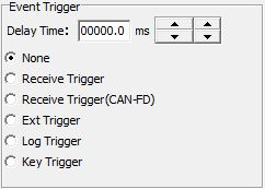
| Item | Description |
|---|---|
| Delay Time | Specify the delay from event detection to transmission. (Note 1) |
| None | No event trigger is used. |
| Receive Trigger | Detects reception of a CAN frame with the specified CAN ID as an event. |
| Receive Trigger(CAN-FD) | Detects reception of a CAN FD frame with the specified CAN ID as an event. |
| Ext Trigger | Detects a port input as an event. (Note 2) |
| Log Trigger | Detects the specified monitoring log as an event. |
| Key Trigger | Detects the specified key input as an event. |
Note 1:  buttons can also increase or decrease the value in increments of 1 or 0.1.
Note 2: Ext Trigger is under development and is not available.
Receive Trigger / Receive Trigger(CAN-FD) Settings
Select Receive Trigger to specify the CAN ID of received frames to detect as events.
For example, you can transmit a frame when a particular CAN ID is received.
Selecting Receive Trigger displays its settings area. Specify the CAN ID of received frames to use as the event trigger.
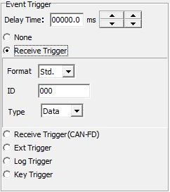
| Item | Description |
|---|---|
| Format | Select a standard ID (Std) or extended ID (Ext). |
| ID | Specify the CAN ID to use as the trigger. |
| Type | Select a data (Data) or remote (Remote) frame. Available for CAN frames only. |
Log Trigger Settings
Select Log Trigger to specify the log to detect as an event.
Log Trigger supports detailed trigger conditions, such as specific data values and error frames.
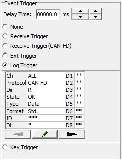
For Log Trigger, click the  button to open the Log Trigger settings dialog. Then click Data Setting to open the Data Setting dialog.
Log Trigger Reference
| Control | Description |
|---|---|
| Settings display | Displays the log information used as the trigger. Double-click to open the Log Trigger settings dialog. |
| button | Click to open the Log Trigger settings dialog. |
Log Trigger Settings Dialog Reference
Specify the log conditions to detect as a trigger.
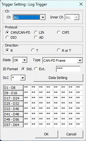
| Item | Description | Settings |
|---|---|---|
| Ch | CH to use as the trigger (MicroPeckerX unit) | Select from the following drop-down options. ALL / 1 / 2 / 3 / 4 |
| InnerCh | CH to use as the trigger (internal MicroPeckerX CH) | Select from the following drop-down options. ALL / 1 / 2 |
| Direction | Specify received/transmitted frames | R: Received frames / T: Transmitted frames / R or T: Both received and transmitted frames |
| State | Specify normal or error frames | Select from the following drop-down options. OK / NG |
| Type | Specify the target frame type | Select from the following drop-down options. [When Status : OK is selected] - CAN-FD Frame - CAN Data Frame - Remote Frame [When Status : NG is selected] - All Error - Bus Error - Error Warning - Error Passive - Bus Off Entry - Bus Off Recovery - Overload - Bus Lock - Arbitration Lost - Stuff Error - Form Error - Ack Error - CRC Error - Recessive Bit Error - Dominant Bit Error - Ack Delimiter Error |
| ID Format | CAN ID selection | Select a standard (Std.) or extended (Ext.) CAN ID. The CAN ID is displayed in Hex. Enter an asterisk (*) to ignore the CAN ID when matching. |
| DLC | CAN data length | Enter an asterisk (*) to ignore DLC when matching. |
| Data Setting button | Open the Data Setting dialog | - |
| Data area | Data area | Displays the data specified in the Data Setting dialog. |
Data Setting Dialog Reference
Click Data Setting in the Log Trigger settings dialog to open the Data Setting dialog.
Specify data conditions for the logs to detect as triggers. Use the tabs to switch between Hex (hexadecimal) and Binary (binary) notation. This dialog configures log matching conditions and is separate from Frame Data - Text Edit, which edits the bytes to transmit.
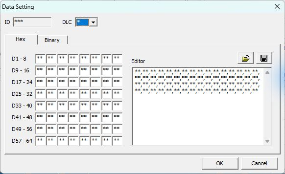
| Item | Description | Details |
|---|---|---|
| ID | CAN ID | The CAN ID cannot be edited in Data Setting. |
| DLC | Data length | The byte entry fields and Editor data area change according to the DLC setting. Enter an asterisk (*) to ignore DLC when matching. |
| Hex / Binary | Display format tabs | Switch the data display between Hex and Binary. |
| Byte entry fields | Data entry area for individual bytes (Note 1) | Each cell holds one byte of data. The upper-left cell is Data1. Enter an asterisk (*) to ignore that data when matching. |
| Editor | Editor area (Note 1) | Enter individual bytes separated by commas. Enter an asterisk (*) to ignore that data when matching. Settings can be saved to and loaded from a CSV file. |
 button | Load a Data Setting settings file | Loads a CSV file saved in Data Setting. |
 button | Save a Data Setting settings file | Saves Data Setting settings to a CSV file. The settings in the Editor are saved. |
Note 1: You can edit data in either the byte entry fields or the Editor. Both displays stay synchronized.
Key Trigger Settings
Select Key Trigger to detect keyboard input as an event.
For example, you can configure frame transmission in response to a key press.
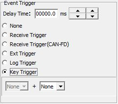
| Item | Description | Details |
|---|---|---|
| Right-hand selection field | Main key setting | Specify the key to use as the trigger. Available keys: 0–9, A–Z, F1–F12, SPACE |
| Left-hand selection field | Modifier key setting | Specify a modifier key to combine with the main key. Available keys: Shift, Ctrl, Alt |
Direct Transmission
Direct Transmission lets you transmit the configured frame manually.
With Send Frame selected in Simulation Window, enable Direct Transmit to use this feature.
During monitoring, click Send to transmit the configured frame.

| Item | Description |
|---|---|
| Protocol | Select CAN or CAN FD. Select from the following drop-down options. - CAN - CAN-FD |
| Std./Ext. | Select a standard ID (Std) or extended ID (Ext). |
| ID | Specify the CAN ID in Hex. |
| Type | Select a data (Data) or remote (Remote) frame. Available only when Protocol is set to CAN. This field cannot be edited when CAN-FD is selected. |
| DLC | Specify the DLC. Select from the following drop-down options. - When Protocol is CAN: 0,1,2,3,4,5,6,7,8,9,10,11,12,13,14,15 - When Protocol is CAN-FD: 0,1,2,3,4,5,6,7,8,12,16,20,24,32,48,64 |
| Data Set button | Specify the frame data. Click Set to open the Data Setting dialog. |
| Bit Rate Switch | Available when a CAN FD frame is selected. - Checked: Use the baud rate configured in Device Window for the CAN FD data phase. - Unchecked: Do not use the CAN FD data-phase baud rate configured in Device Window. Use the arbitration-phase baud rate throughout the frame. |
| Send button | Click during monitoring to transmit the configured frame. The button is unavailable while monitoring is stopped. |