Product Configuration and Feature Overview
Product Configuration
This product is used with the following components.
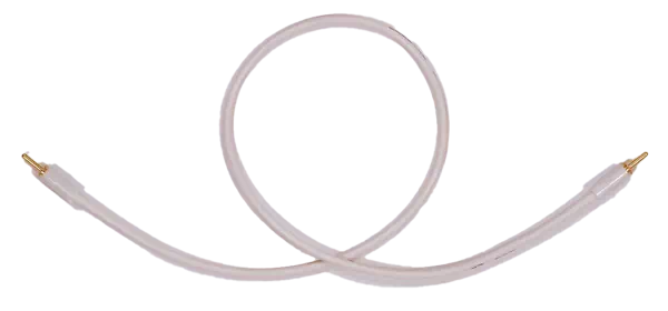
1 x Sync cable
* Not used with MicroPeckerX InstaGW
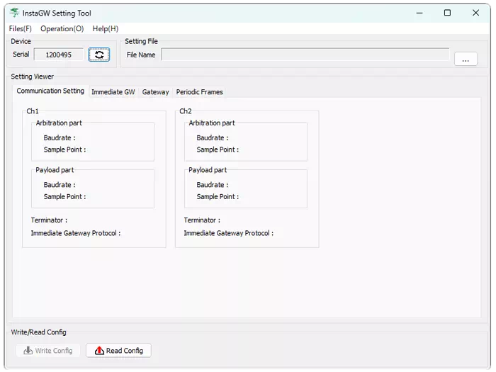
InstaGW Setting Tool
(GUI application)
* Download from the Sunny Giken website
Feature Overview
This product provides the following features.
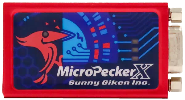
MicroPeckerX InstaGW (MicroPeckerX Main Unit)
| No. | Feature | Overview |
|---|---|---|
| 1 | CAN/CAN FD communication (2 channels) | Supports 2-channel CAN and CAN FD communication. |
| 2 | Standalone operation | Can operate without a PC by using an external power source such as a mobile battery. |
| 3 | Immediate gateway operation | When a frame with specified channel, ID, and DL is received, a frame with the same ID is immediately transmitted on the other channel using the protocol specified for that channel. |
| 4 | Standard gateway operation | When a frame with specified channel, protocol, ID, and DL is received, a frame with the same ID is transmitted on the other channel using specified protocol and DL. Transmission timing can also be offset as needed. |
| 5 | Cyclic transmission | Periodically transmits frames with specified channel, protocol, ID, DL, and data. Alive counters and checksums can be embedded in data. |
| 6 | ID filtering | Only frames with specified IDs on one channel can be forwarded to the other channel. |
Configuration Software (PC Software for MicroPeckerX InstaGW)
| No. | Feature | Overview |
|---|---|---|
| 1 | GW setting file import | Can load an Excel file containing settings for gateway and cyclic transmission on MicroPeckerX. |
| 2 | GW setting write | Can write settings loaded from a GW setting file to MicroPeckerX. |
| 3 | GW setting read | Can read settings currently written to MicroPeckerX. |
System Configuration
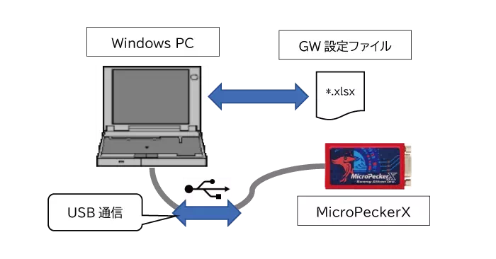
During GW Configuration Using a PC
When configuring GW, use a Windows PC to write the GW setting file content to MicroPeckerX.
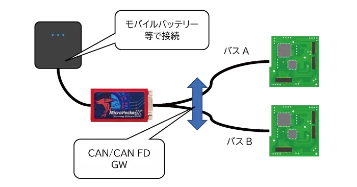
During GW Operation
During GW operation, gateway communication is performed between each CAN bus (Bus A, Bus B, etc.) based on the setting file.
Device Connection
During GW Configuration Using a PC
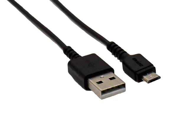
Use the included USB cable to connect MicroPeckerX to a USB port on the PC.
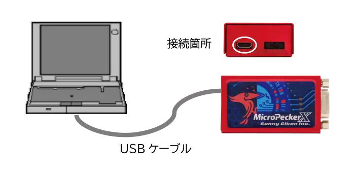
Only the left USB port can be used. Do not remove the cap on the right side.
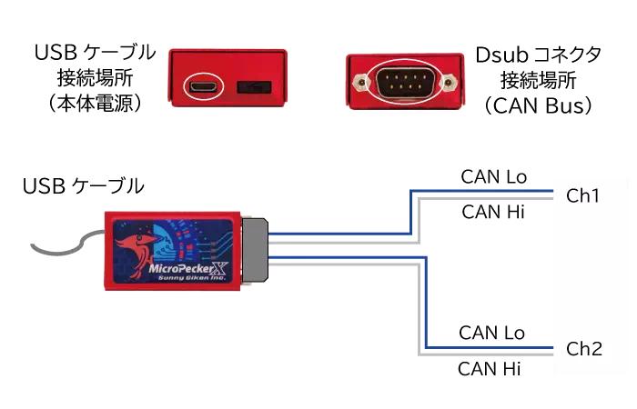
During GW Operation
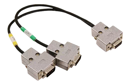
Use the included CAN 2ch Dsub cable to connect each channel to each CAN bus. During GW operation, MicroPeckerX runs in standalone mode, but the main unit still requires USB power.
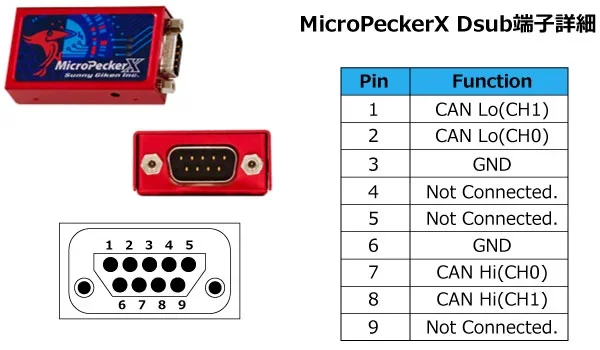
Dsub Connector Details
Dsub connector assignments are shown below.
MicroPeckerX Main Unit
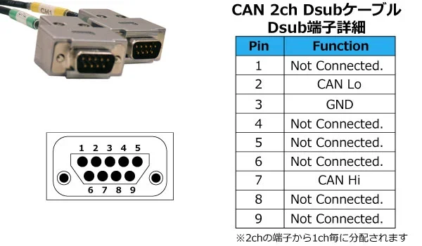
CAN 2ch Dsub Cable (Ch1 and Ch2 Connector Side)
Operating Environment
The required PC environment for the configuration software is as follows.
| Item | Requirement |
|---|---|
| OS | Windows 11 (64-bit), Windows 10 (64-bit) |
| CPU | Intel Core i3 or higher |
| Storage | At least 100 MB free space |
| Memory | 4 GB or more |
| USB port | USB 2.0 (Hi-Speed) compatible |
| Display | 1024 x 768 or higher |
Terminology
Terms used in this manual are defined below.
| Term | Description |
|---|---|
| CAN | Abbreviation of Controller Area Network. A communication protocol developed for in-vehicle networks and standardized by ISO 11898. |
| CAN FD | Abbreviation of CAN with Flexible Data-rate. An extended CAN protocol enabling higher speed and larger payloads, standardized as ISO 11898-1:2015. |
| MicroPeckerX | Generic name for hardware systems equipped with in-vehicle communication interfaces, used together with application software for tasks such as data acquisition and analysis. |
| Arbitration | Identifier (ID) field at the beginning of a CAN frame. If multiple nodes request transmission simultaneously, bus access priority is determined by ID. |
| Payload | Data field in a CAN frame where raw data (signal values) is stored. Up to 8 bytes for CAN and 64 bytes for CAN FD. |
| Ch | Abbreviation of channel. Refers to a physical or logical communication path on the CAN bus. MicroPeckerX can use multiple channels independently. |
| GW | Abbreviation of gateway. Hardware or software that relays data between networks using different communication protocols. |
| GW setting file | Excel (.xlsx) file that contains settings for MicroPeckerX to operate as a gateway device. |