Product Configuration and Functional Overview
Use monitoring to inspect frames, signal values, and waveforms; analysis to investigate recorded communication logs; and simulation to transmit to a test bus. Choose the required operation in the Task-based Guide.
Changes in Ver.4.10
- Change the display language for MPXAnalyzer and standard plug-in messages and explanatory text.
- Auto arrange unassigned signals on a graph while keeping existing assignments.
- Select a Signal Set for analysis in Signal Analysis, then run Analyze with the new Set.
- Export signal values to CSV. Check how many selected signals have samples in the export range and review the preview. By default, rows are exported when the value or validity changes.
- A LIN header on its own does not update signal values or create a signal sample in analysis. It remains visible in the frame log.
See the Revision History for display fixes.
What Changed in Ver.4.00
- New features: Definition management with Signal Catalog; monitoring signal values, waveforms, and alerts; Signal Analysis of saved logs; and signal-based log recording.
- Changes from the previous version: Register the LDF in Catalog, then use its schedules in Master transmission settings or its responses in Slave transmission settings. Registration and starting operation are separate steps.
See Transmission Settings from Catalog and Manual Revision History.
Product Configuration
Use this product with the following components.
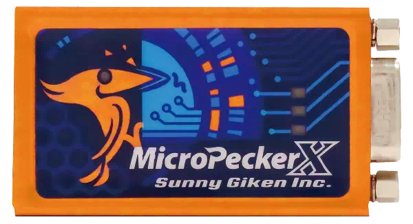
MicroPeckerX LIN Analyzer Plus
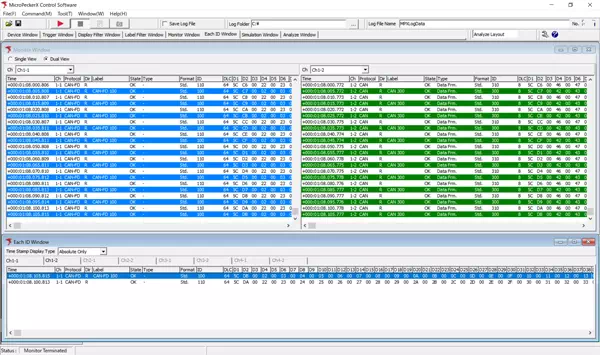
MicroPeckerX Control Software (GUI application)
Download from the Sunny Giken website
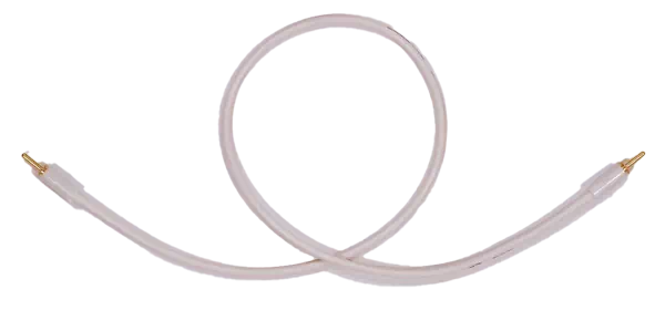
LIN Cables
Use the following LIN cable as needed.
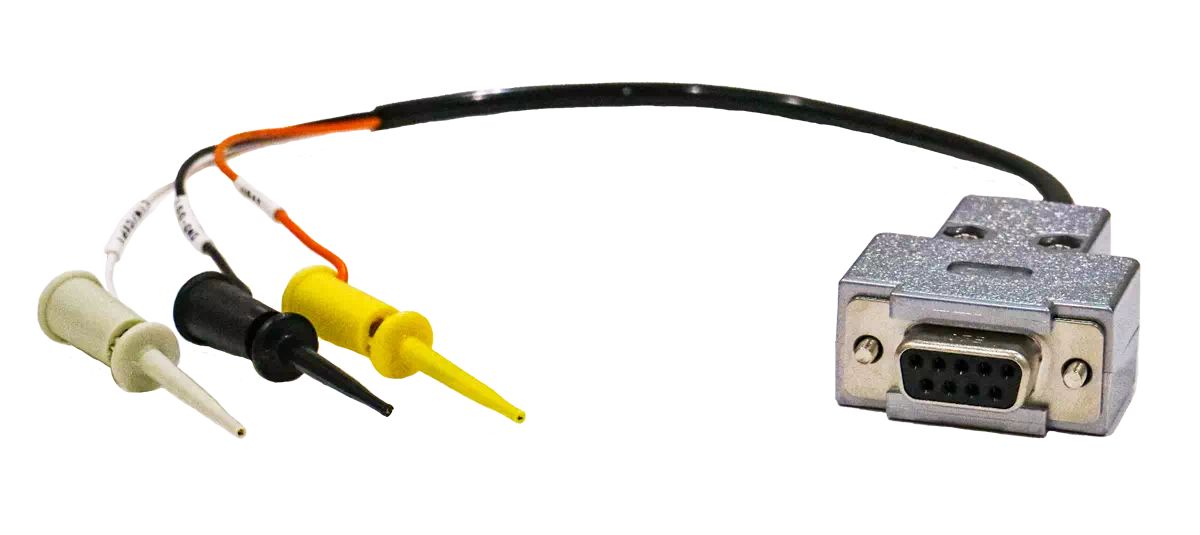
S810-MX-CB3Functional Overview
This product provides the following functions.
MicroPeckerX LIN Analyzer Plus
| Function | Overview |
|---|---|
| Monitoring | Real-time monitoring of frame data on connected LIN bus. - Logging start/stop control by trigger detection - Output frame filtering - Labeling/highlighting for arbitrary frames - Fixed monitor display for identical IDs |
| Signal functions | Monitor and analyze communication data as signal values using LDF files or manually registered signal definitions. - Real-time display of signal values and states, and waveform graphs - Derived signal calculations and alert notifications - Signal analysis of saved logs - Starting and stopping log recording with signal conditions See Signal Monitoring and Signal Analysis for details. |
| Simulation | Various transmission modes are available. 1. Master Simulation - Schedule transmission - Interrupt transmission 2. Slave Simulation 3. Log Replay mode |
| Analyze | Supports loading and analysis of log data. - Automatic/manual log loading - Data search - Filter display - Channel log merge |
System Configuration Diagram
Example System Configuration
An example system configuration is shown below.
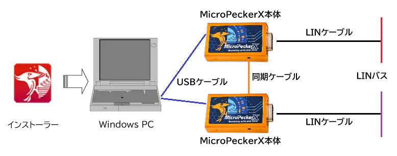
| Device | Notes |
|---|---|
| Windows PC | Used to configure LIN monitor conditions and run GUI application that displays LIN monitor data. |
| Installer | Required for software (GUI application, USB driver) installation and version updates. |
| MicroPeckerX main unit | Connect to PC with USB cable and to LIN bus with LIN cable. When using multiple units, connect units to each other with sync cable. |
| LIN cable | Cable used to connect MicroPeckerX main unit to LIN bus. |
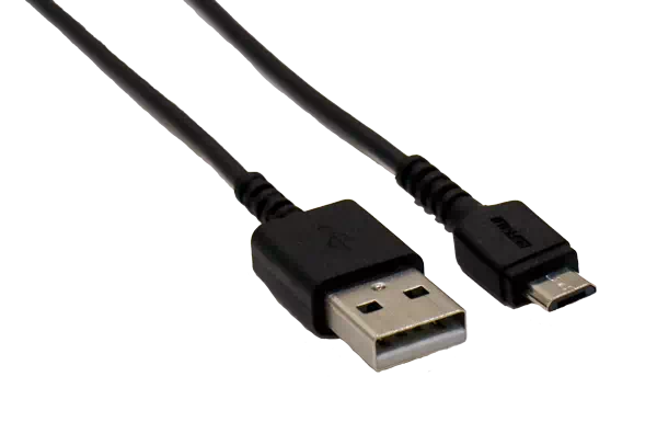
| USB cable | Cable used to connect MicroPeckerX main unit to PC. Connector type is A-microB and supports USB2.0. |
| Synchronization cable | A cable for synchronizing multiple MicroPeckerX units. |
Operating Environment
The required PC environment for configuration software is as follows.
| Item | Requirement |
|---|---|
| OS | Windows 11 (64bit), Windows 10 (64bit), Windows 8.1 (64bit) [*1] [*2] |
| CPU | Intel or AMD x86 processor (Core i5/Ryzen5 or higher recommended) |
| Hard Disk | 10Gbyte or more free space [*3] |
| Memory | 8Gbyte or more recommended |
| USB Port | USB2.0 (Hi-Speed), with enough ports for the number of connected MicroPeckerX units [*4] |
| Display | 1920×1080 or higher recommended |
| Other | Monitor, keyboard, mouse |
[*1]: On PCs with power-saving features, configure settings so that sleep, HDD stop, and CPU clock reduction do not occur while using this product.
[*2]: Operation in virtual environments is not supported.
[*3]: For long-duration monitoring, ensure sufficient hard-disk free space.
[*4]: When using an external USB hub, use a self-powered device and connect it with external power supplied.
(If a bus-powered USB hub is used, operation may fail or become unstable.)
Terms
The terms used in this document are described below.
| Term | Description |
|---|---|
| LIN | Abbreviation of Local Interconnect Network. Communication protocol developed to reduce cost of in-vehicle networks. International standard defined by ISO 17987. |
| DIO | Abbreviation of Digital Input/Output. Electrical signal used to determine external status with binary values ON (1) and OFF (0). |
| A/D | Abbreviation of Analog/Digital. Means conversion of analog signals into digital signals. This product can acquire voltage values by converting them into digital signals. |
| MicroPeckerX | A hardware system with one channel each of LIN and DIO/AD. Used with this application. |
| Ch | Abbreviation of Channel. Physical or logical communication path such as LIN bus. MicroPeckerX can use multiple channels (for example Ch1-1, Ch2-1), each transmitting and receiving independently. |
| Monitoring | Real-time display on GUI application of data captured from LIN bus, etc. |
| Logging | Automatic saving of data captured from LIN bus, etc., to specified PC folder in text file (.csv) format. |
| Physical Value | A numeric value obtained by converting a Raw value using factors, offsets, or other operations. The conversion formula is specified in the definition; changing only the display unit does not convert the value. |
| Signal Value | A value obtained by extracting bits from a frame according to a definition and converting them as needed. The unconverted value is called the Raw value, the converted numeric value the physical value, and a state name the Logical value. |
| Log replay | A function that reproduces or replays the contents of a recorded log file. |
For the relationships among Signal Catalog, Signal Sets, and derived signals, and the preparation procedure, see Signal Function Overview.