Slave Simulation
The slave simulation function allows operations such as transmitting responses to headers received from the master node.
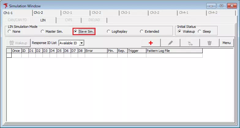
Select **Slave Sim.** in LIN Simulation Mode of Simulation Window to use the slave simulation function.
Basic Operation of Slave Simulation
This section explains the setup flow for slave simulation.
- Select Slave Sim. in Simulation Window
SelectSimulation Windowfrom the menu or toolbar, then select**Slave Sim.**fromSimulation Mode.
This enables the slave simulation function.
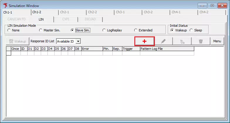
- Open the LIN Response Setting dialog
Click the button in Simulation Window.
This displays the LIN Response Setting dialog.
- Configure response information
Configure response information inFrame Settingof the LIN Response Setting dialog.
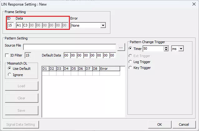
The minimum required settings and an example are shown below.
| Item | Description | Example |
|---|---|---|
| ID | Enter the LIN ID. | 15 |
| Data | Enter the response data. | A1 C3 |
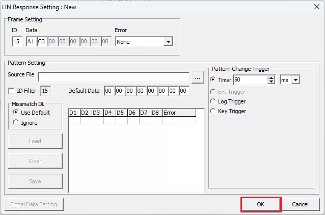
- Register response information
Click the button in the LIN Response Setting dialog.
The configured response information is registered and displayed in the response list ofSimulation Window.
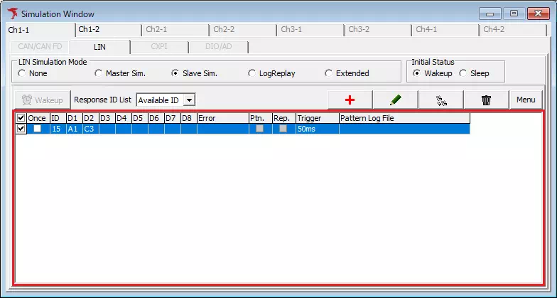
If you turn OFF the leftmost check box in the response list of Simulation Window, the registered response information is treated as disabled, and the corresponding response is not transmitted even if a header with the configured ID is received.
The check box state can also be changed during monitoring.
- Start monitoring
Click the button on the toolbar (you can also select
 Command-Startfrom the menu bar or pressF5).
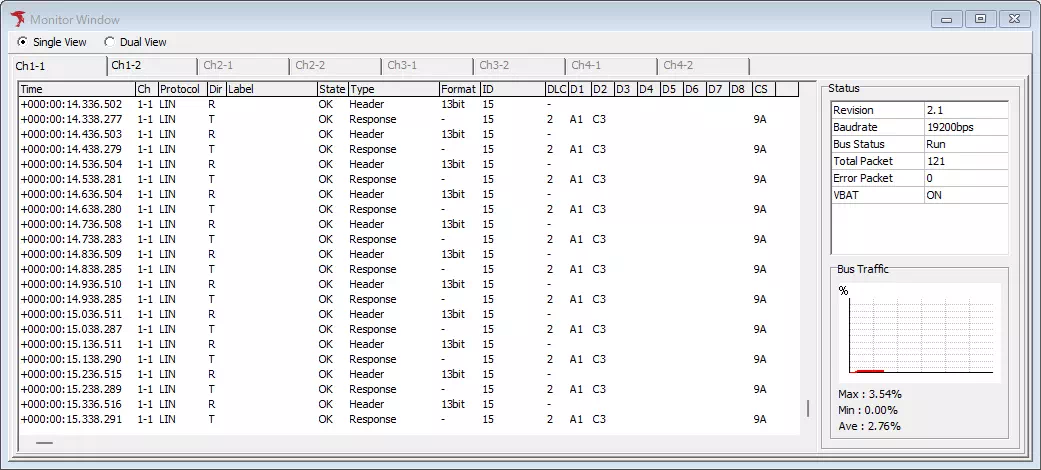
Monitoring starts, and when a header with the ID of registered response information is received, the corresponding response is transmitted.
Screen Description of Slave Simulation
| Screen menu | Description | Notes |
|---|---|---|
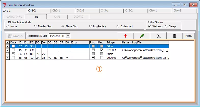
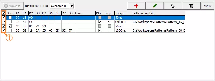
| Response List (Area 1) | Displays the configured response information. | See Response List for details. |
| Response ID List | Sets the display format of Response List. The pull-down options and their meanings are as follows.Available ID: Displays only IDs for which response information is registered.ALL ID: Displays all IDs. Rows for IDs with no registered response information are shown with gray hatching. | |
| button | Click to open the LIN Response Setting dialog and register new response information. | If Response ID List is set to ALL ID, you can also register new response information by double-clicking a row in Response List that does not have response information registered, excluding the check box cell.You cannot register new response information during monitoring. |
 button button | Click to open the LIN Response Setting dialog and edit the response information selected in Response List. | You can also edit response information by double-clicking a row in Response List with registered response information, excluding the check box cell.Response information can also be edited during monitoring. |
 button button | Click to open the LIN Response Setting dialog and register a new response information entry based on the response information selected in Response List. | This button cannot be clicked during monitoring. |
 button button | Click to display the following dialog. Clicking Yes deletes the response information selected in Response List.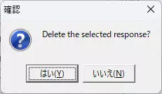 | This button cannot be clicked during monitoring. |
 button button | Click to transmit a wakeup signal. | This button can be clicked only during monitoring. |
 button button | Click to display the following menu.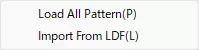 Selecting Load All Pattern loads in bulk the pattern files configured for response information whose Ptn. check box is ON in Response List.Selecting Import From LDF imports the response information in Response List in bulk from the loaded LDF file. At that time, all response information registered before the import is deleted. |
Response List
Displays the registered response information. You can also configure whether responses are enabled and whether pattern data is repeated.
| Item | Description | Notes |
|---|---|---|
| Valid (Area 1) | Sets whether the response is transmitted. If the check box is OFF, that response is not transmitted. | |
| Once | Sets whether the response is transmitted repeatedly. If the check box is ON, that response is transmitted only once during monitoring and is not transmitted again until monitoring is stopped. | |
| ID | Displays the LIN ID of the response in hexadecimal. | |
| D1-D8 | Displays the per-byte data of the response in hexadecimal. | |
| Error | Displays the error type of the response. | |
| Ptn. | Sets whether to use a pattern file for the per-byte data of the response. The meanings of the ON/OFF check box state are as follows.ON: Uses Pattern Setting in the LIN Response Setting dialog.OFF: Uses Frame Setting in the LIN Response Setting dialog. | If the pattern file to load is not configured, the check box is disabled. |
| Rep. | Sets whether to apply the pattern data list repeatedly. The meanings of the ON/OFF check box state are as follows.ON: When a pattern change event occurs after reaching the bottom of the pattern data list, processing returns to the top.OFF: Once the bottom of the pattern data list is reached, pattern change events remain disabled until monitoring stops. | If the pattern file to load is not configured, the check box is disabled. |
| Trigger | Displays the occurrence condition of the pattern change event. | |
| Pattern Log File | Displays the file name of the pattern file to load. |
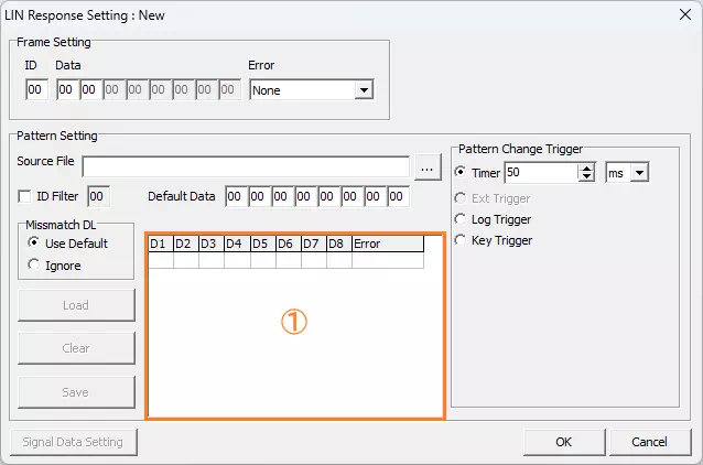
LIN Response Setting Dialog
You can configure response information.
| Item | Description | Notes | |
|---|---|---|---|
| Frame Setting | ID | Sets the LIN ID of the response in hexadecimal. The configurable range is 00H-3FH. | If you set a value outside the configurable range (40H or higher), it is automatically corrected to the value shifted right by 8 bits. For example, if you set 57H, it is corrected to 05H. |
| Data | Sets the per-byte data of the response in hexadecimal. | The configurable byte count is adjusted automatically based on the LIN ID set in ID and the ID definition configured in the ID Definition tab of Device Setting. | |
| Error | Sets whether the response has an error and the error type. The pull-down options are: None, CheckSum, ShortMsg. (1Byte), ShortMsg. (2Byte), ..., ShortMsg. (8Byte), Framing(Data1), Framing(Data2), ..., Framing(Data8), Framing(CS) | If either of the following applies, the configured error is invalid and is treated as None.- A ShortMsg. byte count larger than the data length of the ID definition is configured, such as ShortMsg. (3Byte) for an ID whose data length is 2.- A Framing byte position larger than the data length of the ID definition is configured, such as Framing(Data3) for an ID whose data length is 2. | |
| Pattern Setting | Source File | Displays the full path of the pattern file selected as the load target in the file dialog from the  button. button. | You can also configure the pattern file to load by entering the full path directly. |
| button | Click to display the file dialog and select the pattern file to load. | The selected pattern file is not loaded until you click the  button. button. | |
| ID Filter | Sets whether to extract pattern data contained in the loaded pattern file. If the check box is ON, pattern data that does not satisfy any of the following is treated as invalid and is not shown in the pattern data list. - The ID matches the value displayed in ID Filter (the value configured in ID in this dialog)- The type is Wakeup- The type is Sleep | ||
| Default Data | Sets the default data in hexadecimal to use when the ID definition configured in the ID Definition tab of Device Setting does not match the data length of pattern data contained in the loaded pattern file. | ||
| Missmatch DL | Sets the handling when the ID definition configured in the ID Definition tab of Device Setting does not match the data length of pattern data contained in the loaded pattern file. The radio button options and their meanings are as follows.Use Default: If the data length of the ID definition is larger than the target pattern data, default data is used for the missing part of the pattern data.Ignore: The target pattern data is treated as invalid and is not shown in the pattern data list. | An example when Use Default is configured is shown below.ID definition data length: 4 bytes Pattern data in the pattern file: 08,4C (2 bytes) Default data: 11,22,33,44,55,66,77,88 In this case, default data is used for the third and fourth bytes of the pattern data, so the pattern data becomes 08,4C,33,44. | |
| button | Click to load the pattern file displayed in Source File and display the pattern data contained in the pattern file in Pattern Data List. | ||
 button button | Click to clear all pattern data displayed in Pattern Data List. | ||
 button button | Click to display the file dialog and save the pattern data displayed in Pattern Data List as a pattern file with any file name. | ||
| Pattern Data List (Area 1) | Displays the pattern data contained in the loaded pattern file. | ||
| Pattern Change Trigger | Sets the occurrence conditions of pattern change events. For the radio button options and their meanings, see Pattern Change Trigger. | ||
| button | Click to save the configured response information and close the dialog. | ||
 button button | Click to discard the configured response information and close the dialog. | ||
The title bar of the dialog changes depending on the operation used to display it.
| Operation | Title |
|---|---|
| Click the button |  |
| Click the button |  |
| Click the button |  |
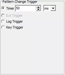
Pattern Change Trigger
You can configure the occurrence conditions of pattern change events.
| Item | Description |
|---|---|
| Timer | An event occurs each time the configured time elapses. |
| Ext Trigger | An event occurs by external port input. This function is currently under development and cannot be used. |
| Log Trigger | An event occurs when the configured log is detected. |
| Key Trigger | An event occurs on the configured key input. |
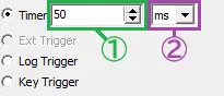
Timer
| Screen menu | Description | Notes |
|---|---|---|
| Time value (Area 1) | Together with the time unit, sets the cycle at which pattern change events occur. The configurable range depends on the selected time unit as follows.ms (milliseconds): 50-3600000 (multiples of 50 only)sec (seconds): 1-3600min (minutes): 1-60 | When changed with the spin button, the value increases or decreases in 50-millisecond increments only when the time unit is set to ms. |
| Time unit (Area 2) | Together with the time value, sets the cycle at which pattern change events occur. The pull-down options are: ms, sec, min |
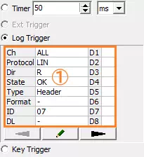
Log Trigger
| Screen menu | Description |
|---|---|
| Event condition (Area 1) | Displays the log information configured as the occurrence condition for a pattern change event. Double-clicking this area displays the Trigger Setting dialog, where you can configure the log information for the event condition. |
 button button | Click to display the Trigger Setting dialog and configure the log information for the event condition. |
For details on the Trigger Setting dialog, see Screen Description of the Trigger Setting Dialog.
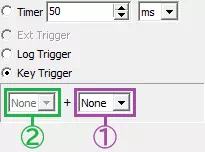
Key Trigger
| Screen menu | Description | Notes |
|---|---|---|
| Main key (Area 1) | Sets the key used as the event condition. The pull-down options are: None, A, B, ..., Z, 0, 1, ..., 9, F1, F2, ..., F12, SPACE | If None is set for the main key, no key-input event occurs. |
| Sub key (Area 2) | Sets the sub key used together with the main key as the event condition. The pull-down options are: None, Alt, Ctrl, Shift Set None when a sub key is not used. | It is not possible to detect an event using only the sub key. |