Device and Functional Specifications
MicroPeckerX Hardware Specifications
| Item | Description |
|---|---|
| Power supply | USB Bus Power (5V, 300mA) |
| Dimensions | 65(W)×35(D)×16(H)mm |
| Weight | 45g |
| LED | 4 LEDs Orange: Power status (lit when powered) Green: Communication Ch1 (blinks during LIN communication on Ch1) Yellow: VBAT status (blinks when VBAT is supplied) Red: Error (lit on abnormal event) |
| Synchronization interface | 2 interfaces |
| LIN interface | DSub 9pin, 1ch |
| VBAT supply | External supply through D-Sub 9-pin connector |
| VBAT input voltage range | 8–24V (absolute maximum rating: 40V) / 100mA or less |
| Hardware protection | ESD, reverse polarity, and overcurrent protection circuits |
| USB ports | 2 USB Micro-B ports (main, sub) |
International Standards
- CE marking acquired
EMI: EN55011(2020) Group1 ClassB
EMS: EN61000-4-2(2009), EN61000-4-3(2010) - FCC compliant
This device complies with Part 15 of the FCC Rules. Operation is subject to the following two conditions:
(1) This device may not cause harmful interference, and (2) This device must accept any interference received, including interference that may cause undesired operation.
Front View

Top and Bottom Views

Left and Right Side Views

Note: Do not use the sub USB port.
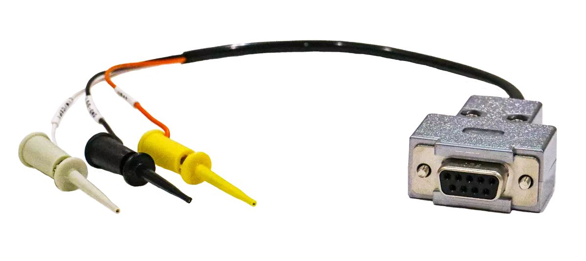
LIN 1ch Clip Cable Specifications
| Item | Description |
|---|---|
| Signals | LIN, VBAT, GND Note: Uses clip connectors |
| Cable length | Total length: 0.3m |
| Shield | None |
Connector Terminals
Synchronization Cable Specifications
| Item | Description |
|---|---|
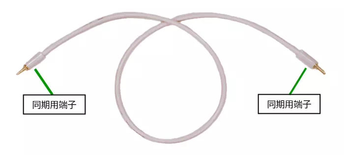
| Cable length | Total length: 25cm |
| Shield | None |
MicroPeckerX LIN Analyzer Plus Functional Specifications
| Item | Description | |
|---|---|---|
| LIN Interface | 1ch | |
| Supported channels | LIN 1ch per unit; up to LIN 4ch (4 units) can be connected simultaneously | |
| Multi-channel synchronization | Monitor timestamp synchronization | Supports monitor data time synchronization of up to 4 MicroPeckerX units combining CAN (CAN FD), LIN, DIO, and AD |
| Simulation transmission timing synchronization | Supports simulation timing synchronization of up to 4 MicroPeckerX units combining CAN (CAN FD), LIN, DIO, and AD | |
| Log replay transmission timing synchronization | Supported | |
| LIN Communication Settings | Supported Revision | LIN 1.3 / 2.0 / 2.1 / 2.2 / 2.2A |
| Baud Rate | In addition to the following options, custom settings are available from 500bps to 20kbps in 1bps increments. | |
| LIN Monitoring Function | Timestamp Resolution | 1μsec |
| ID/Data Display | Real-time display of various IDs and data values | |
| Frame type | Header / response / error frame display supported | |
| Error Frame Detection | SyncBrk.Long、SyncBrk.Short、SyncBrkField、Parity、CheckSum、ShortMsg.(1~8)、Framing | |
| Timestamp Format | Selectable: +MM:SS:HHH.mmm.uuu / +SSSSSSSS.mmmuuu | |
| LIN Log Type | Selectable: Header+Response / LIN Frame | |
| Display Filter | LIN ID condition setting supported | |
| Label Filter | Conditions available for LIN ID / Tx-Rx frame / Status / Header / Response / Wakeup / Sleep / B-Sleep | |
| Each ID Display | Latest log display per ID | |
| Log Output Destination | File, on-screen display (up to 100,000 records) | |
| Log Format | Text (CSV), hexadecimal output | |
| Log Split Output | No splitting, file size (1MB–4095MB), records (100–2.5 million lines), timer (1sec–3600sec) | |
| Log Trigger Mode | Free RUN, Start Trigger, Stop Trigger | |
| Log Trigger Conditions | Reception of a specified frame, key input, signal threshold conditions | |
| Common Node Simulation Functions | Transmission time resolution | 1msec |
| Status at Monitor Start | Wakeup/Sleep selectable | |
| Master Simulation Transmission Functions | Number of Schedules | Up to 32 |
| Schedule Name | Up to 14 characters | |
| Schedule Settings | Enable/disable, repeat | |
| Schedule Transition Event Types | Timer (50ms to 24hour), Log Trigger, Key Trigger, user switch | |
| Schedule Operations | Pause, schedule switch, ID change during transmission | |
| Configurable frame count | Up to 64 frames | |
| Transmission Delay | Configurable from 1ms to 3,600,000ms (1 hour) | |
| Frame type | Transmit, receive, wakeup pulse, sleep command Error settings available for transmit and receive | |
| Header Error Types | SyncBrk.Long、SyncBrk.Short、SyncBrkField、Parity | |
| Response Error Types | CheckSum、ShortMsg.(1~8)、Framing(1~CS) | |
| Pattern File | Configurable per ID | |
| Pattern File Event Types | Timer (50ms to 60min), frame reception trigger, key trigger | |
| Interrupt Transmission Frame Count | Up to 16 frames | |
| Interrupt Frame Types | Transmit, receive, wakeup pulse, sleep command Error settings available for transmit and receive | |
| Interrupt Trigger Types | Frame reception trigger, key trigger, none | |
| Wakeup Wait | Configurable from 0ms to 100ms | |
| Slave Simulation Transmission Functions | Configurable frame count | Up to 64 frames |
| Frame type | Response transmission Error settings available for response | |
| Response Error Types | CheckSum、ShortMsg.(1~8)、Framing(1~CS) | |
| Pattern File | Configurable per ID | |
| Pattern File Event Types | Timer (50ms to 60min), frame reception trigger, key trigger | |
| Log replay transmission | Transmission time resolution | 1msec |
| First-frame transmission offset | Configurable from 0ms to 60000ms | |
| Log replay start timing | Monitor start, frame reception trigger, key trigger | |
| Transfer mode | Repeat mode, single transfer mode | |
| LDF Import | Registration and use of definitions | Register signals, frames, and schedules in Signal Catalog. In Simulation Window, apply schedules to Master Sim. or responses to Slave Sim. |
| Log analysis | Analysis Targets | Frame and signal analysis of communication logs |
| Filtering | ID / error frame / label setting supported | |
| Log Search | Timestamp / frame / label setting supported | |
| Bus Load Analysis | Not available for saved logs. Monitor Window displays bus load in real time. | |
| Signal monitoring | Signal capacity | Catalog: up to 10,000 entries; Signal Sets: up to 10; each Set: up to 128 signals (including input signals required by derived signals) |
| Conversion and display formats | Raw, Formula, Value Table, BCD, ASCII. Supports display of physical values and Logical state names. | |
| Signal display during monitoring | Value list, graphs, numeric bars, state display, alert history | |
| Graph capacity during monitoring | Up to 32 signals, 2 tabs, up to 4 Areas per tab, and up to 4 axes per Area (2 left and 2 right) | |
| Capture Function | Monitor Log Capture | None |
Communication Definitions, Signal Analysis, and Transmission Settings
- Signal Catalog imports signal, frame, and schedule definitions from LDF files. See Catalog Limits and Counting Rules.
- Signal Trigger controls recording using thresholds on eligible numeric bus signals. Derived and string signals are excluded. See Selection Conditions.
- Signal Analysis works with recorded communication logs, with an input limit of 5 million frames across all CHs and the entire period. See Signal Analysis for the scope of input and results.
- LDF schedules can be used in Master Sim., and responses published by slave nodes can be used in Slave Sim. See Using Definitions from Catalog.