Setting Schedules and Responses from Catalog
Definitions and Transmission Data
Importing an LDF into Signal Catalog registers communication definitions. Review the Safety Precautions before operating on a test bus. Select and adopt the registered LDF schedules or frames in Simulation to use them in transmission settings. Importing alone does not start transmission.
| Purpose | Operation in Simulation |
|---|---|
| Use LDF schedules | Open Import LIN Schedules from Catalog from the Master Sim. Schedule menu. |
| Use publisher responses | Select the target frames using the Responses from Catalog button in Slave Sim. |
| Edit individual frame values | In Signals in LIN Frame Setting / LIN Response Setting, select a definition and edit initial values. |
The In Set, Values, and Graph ON/OFF states in a monitoring Set do not alone determine what is transmitted. Check the schedules, frames, and responses selected in Simulation.
The following example uses SensorSchedule and SensorFrame from the sample LDF. In Master, import the schedule to create a slot for receiving the SensorNode response; in Slave, create a response and edit its transmission values.
Master: Importing Schedules
- Stop monitoring and use Import in Catalog to import an LDF containing Schedule_tables.
- Select the connected target CH in Simulation Window and set LIN Simulation Mode to Master Sim.
- From Menu on the Schedule tab, open Import LIN Schedules from Catalog... (Figure 1).
- Select Source LDF and check Master and Bitrate.
- Check the schedules to import under Schedules to Import. Select a row and review the order, Delay, Dir., ID, DL, and Data in Selected Schedule Preview.
- Check the destination empty schedule numbers and confirm that import is available, then click Import.
- If a Device setting change confirmation appears, review the current values, requested values, and scope of effects. Choose Apply and Import to proceed, or Cancel to stop.
- After importing, check the Schedule list and each frame, and edit initial values and enabled states as needed.
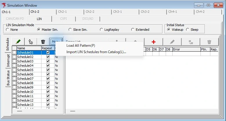
Figure 1: Importing Catalog schedules from the Schedule menu.
This operation adds the selected schedules to empty slots. If there are not enough empty slots or a definition cannot be used, check the reason displayed on screen.
Data for receive entries is shown as “-” and is not transmission data. Initial values for transmit entries are based on the LDF definitions. Check the final data in the frame settings after importing.
In this sample, select signal-example.ldf for Source LDF and SensorSchedule under Schedules to Import (Figure 2). Master is MasterNode and Bitrate is 19200 bit/s (19.2 kbps). Selected Schedule Preview shows one SensorFrame row with Delay 100 ms, Dir. Rx, ID 10 (hexadecimal 0x10), and DL 2. Because the publisher of SensorFrame is SensorNode, there is no response data for the master to transmit.
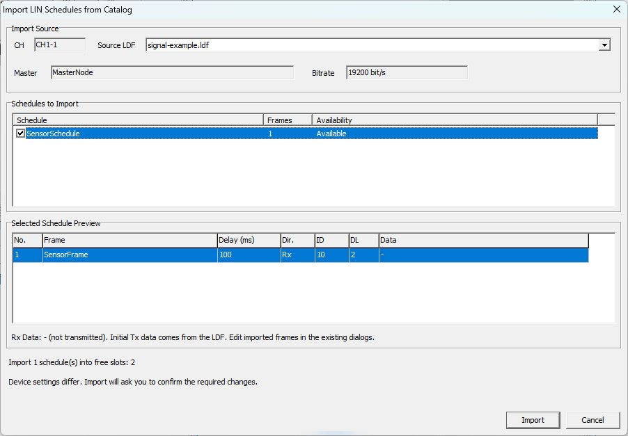
Figure 2: Checking SensorSchedule and the receive-side SensorFrame.
Figure 3 shows confirmation of changing the CH1-1 bitrate from 19841 bit/s to 19200 bit/s. The bitrate change affects all of CH1-1. Check the target CH and changes, then click Apply and Import.
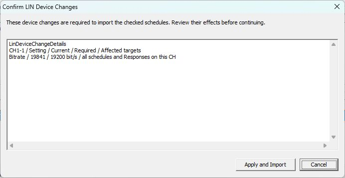
Figure 3: Confirming a bitrate change affecting all of CH1-1.
In Figure 4 after import, SensorSchedule has been added to the empty second slot in the schedule list, separately from the existing Fan_Response. Select the added SensorSchedule and check that Frame List shows Delay 100 ms, Dir. Rx, and ID 10. Confirm DL 2 in the preview in Figure 2. Since the direction is Rx, no transmission data appears in D1 or D2.
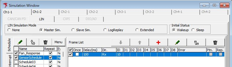
Figure 4: Schedule and Rx frame after importing SensorSchedule.
When No Schedules Are Displayed
Check that schedules are registered in Source LDF. If not, close with Cancel, import the LDF using Catalog on the main toolbar, and reopen the screen. Registering signals and frames alone does not automatically create LDF schedules.
Slave: Creating Responses
- Stop monitoring and register LDF frames in Catalog. In Simulation Window, select the connected target CH and Slave Sim.
- Click Responses from Catalog.
- Select the import source under Source and check candidate IDs, DL, Publisher, and initial data. Do not confuse definitions with the same name from different Sources. Publisher is a reference column. Frames published by the Master are not eligible for response adoption.
- Check the candidates to use. Selecting a row displays details; checking it specifies it for adoption. Checking an existing ID displays Replace Response. Review it and click Replace to include the candidate, or Cancel to retain the existing response.
- Under Responses after Apply, review existing, added, and replaced responses after application. Unchecked responses remain unchanged.
- Click Add N Responses or Apply N Responses, where N is the number of selected responses.
- If Device per-ID DL differs, review the changes and scope in Confirm LIN Device Changes, then click Apply Responses to adopt them. Cancel does not apply them.
- After applying, compare the response list IDs, data from D1 onward, and enabled states. Also check data lengths and other settings in individual settings or Device settings.
Responses being replaced use the Catalog initial data, and their Error and Pattern settings are cleared. Their enabled / disabled state is retained. Reconfigure required Pattern and Error settings after adoption. Unselected responses are not replaced.
Slave response adoption preserves the Device bitrate. Required per-ID DL changes also affect frames, Pattern, and Interrupt with the same CH and ID. Review the effects, and reopen the screen if Catalog or Device setting changes make application unavailable.
In this sample, select signal-example.ldf as Source and check SensorFrame (Figure 5). ID is 10 (hexadecimal 0x10), DL is 2, and Publisher is SensorNode. Check that Data (HEX) in Responses after Apply is “0A 00”, then click Add 1 Responses. In Figure 6 after adoption, a response list row for ID 10 has been created with D1 0A and D2 00.
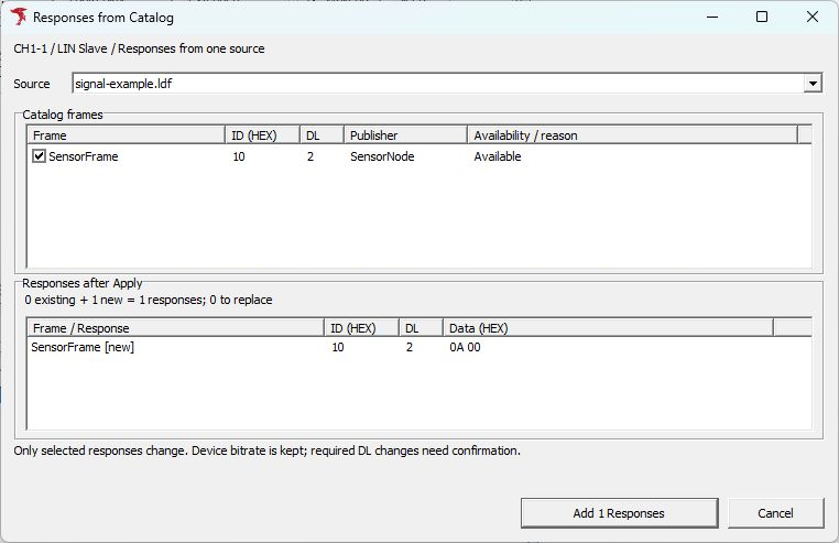
Figure 5: SensorFrame response candidate and initial data after application.
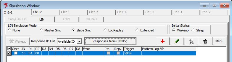
Figure 6: Initial data 0A 00 reflected in the response list.
Editing Initial Values by Signal
Signals is always displayed in LIN Frame Setting / LIN Response Setting. Check the selected definition by its name and signal count. If there are no displayable signals, Raw frame and No signals selected are shown.
- In Master, set Direction to Tx or Rx (definitions cannot be adopted for Wakeup / Sleep). To adopt or reselect a definition, click From Catalog in Signals. In Select LIN Frame from Catalog, check Source LDF, the target frame, and Signal Preview, then click OK. If the response ID is fixed, select a frame with the same ID.
- If Confirm LIN Device Changes appears, review the changes and click Use in Parent Draft to adopt them. The first adoption of a definition for a new transmission frame or response fills in Catalog initial data. Existing frames and responses retain the data currently being edited.
- Choose an available Format (Physical / Logical / Raw signed / Raw unsigned) for the target signal, then edit Initial value. Check the input range and error messages, and compare signal values with D1 (HEX) through D8 (HEX).
- Check ID, data length, Master Direction, selected definition, and converted byte sequence, then click OK in the frame / response settings screen to finalize. Cancel discards the changes being edited.
When a master frame's Direction is Rx, displayed signal values are references for checking the definition's initial values. Transmission values can only be edited for Tx.
Editing the Sample Transmission Values
Open the adopted Slave response with ID 0x10 and set the following values in Signals in LIN Response Setting (Figure 7).
| Signal | Format | Initial value | Corresponding data |
|---|---|---|---|
| Speed | Physical | 10 km/h | D1 (HEX) = 1E |
| State | Logical | On | D2 (HEX) = 01 |
The Speed conversion formula is “Physical value = Raw value × 0.5 − 5”. The Raw value for 10 km/h is 30 (0x1E), and State On is 1 (0x01). Check that D1 (HEX) and D2 (HEX) are “1E 01”, then click OK to finalize. Also verify that D1 and D2 in the response list have changed to 1E and 01 (Figure 8).
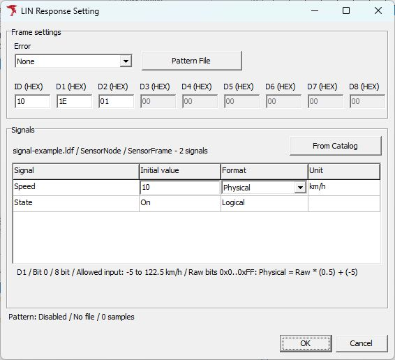
Figure 7: Editing Speed to 10 km/h and State to On, and checking 1E 01.
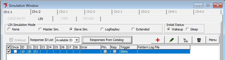
Figure 8: Edited response data 1E 01.
Also check bits not used by signals, data length, and checksum conditions. Derived signals are not targets for editing initial data bits.
Do not assume that editing Catalog alone automatically updates adopted definitions or transmission data. To use an updated definition, adopt it again and check initial values, ID, and data length.
Device Settings and Pre-transmission Checks
If the LDF and Device settings differ, importing Master schedules may require bitrate and per-ID data length changes, while adopting Slave responses may require per-ID data length changes. Slave preserves the existing bitrate. Bitrate affects all schedules and responses on the same CH, while per-ID data length affects frames, Pattern, and other settings with the same ID. Review the displayed scope of effects.
In Device Window, compare bitrate, per-ID DL, checksum, and LIN revision with the connected system's specifications. Confirm that the test bus is safe and check the roles of the other nodes.
Configure Schedule Enablement and Transmission Conditions in Master or Response Enablement and Response Conditions in Slave. Slave responds to target headers from the other master. Creating a response alone does not make it transmit spontaneously.
Save settings using Normal Configuration Saving, and save all communication definitions using Catalog MPXSIG Saving. After transmission, compare Monitor Window and Signal Window, and inspect recorded logs in Signal Analysis.