Choosing a Simulation Mode and Basic Operations
| Purpose | Configuration path |
|---|---|
| Use schedules from an LDF | Import from Catalog into Master |
| Use responses from an LDF | Responses from Catalog |
| Create frames or responses directly in HEX or other formats | Manual settings in Master / Slave |
| Retransmit a communication log to an actual bus | Log Replay |
| Change response data sequentially | Pattern Files |
Registering definitions in Catalog, using them in transmission settings, and starting operation are separate actions. Before transmitting, review the Safety Precautions and the effects on the connected system.
For creating transmission settings from communication definitions and editing initial values in Physical / Logical / Raw formats, see Linking Signal Definitions and Transmission Settings. To verify signal values in recorded logs, see Signal Analysis.
Functional Overview
In MicroPeckerX LIN Analyzer Plus, transmission settings to LIN bus can be configured in Simulation Window.
| Function | Description |
|---|---|
| Simulation modes | Choose from: None (monitoring only), Master Sim. (master simulation), Slave Sim. (slave simulation), LogReplay (log replay), Extended (plugin extension) |
| Master Simulation (Master Sim.) | Operates as master node and provides: - Schedule transmission (automatically transmits frames according to configured schedule) - Interrupt transmission (transmits arbitrary frames triggered by key input, etc.) |
| Slave Simulation (Slave Sim.) | Operates as slave node and can transmit per-ID responses to headers received from master node. |
| Log replay (Log Replay) | Loads LIN records to replay from a communication log CSV and replays them as a master node according to per-ID Tx / Rx and other replay settings (up to 3 million records). The following settings are also available: - Loop replay - Interval from the start of monitoring to the first frame transmission - Start transmission upon log detection or key input |
| Pattern files | In Master Simulation and Slave Simulation, load a pattern file to set response data and change it using elapsed time or other triggers. |
These options make it easy to reproduce real-world frame transmission, test bus loads, recreate scenarios, and perform manual debugging with a variety of patterns.
Simulation Window Description
In Simulation Window, select the Ch and LIN Simulation Mode to use, then configure each mode. Figures 1–5 all show Ch1-1 settings while monitoring is stopped. Before operating, check the transmission contents and start conditions in the details for each mode.
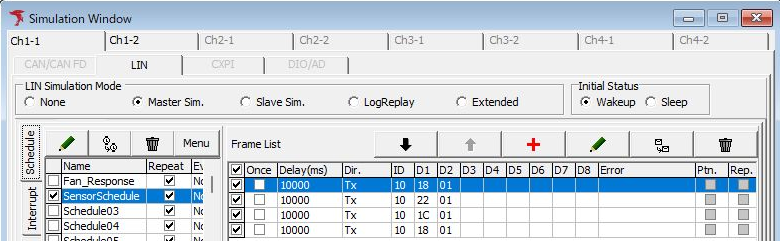
Figure 1: Ch, mode, and Initial Status selection in Simulation Window.
| Item | Description |
|---|---|
| Channel selection tabs | Select the channel to use. Figures 1–5 show Ch1-1. |
| LIN Simulation Mode | Select the Simulation Mode to use. The radio button options are: 【None】 Monitor mode (no frame transmission) 【Master Sim.】 Master simulation mode (operates as a master node) 【Slave Sim.】 Slave simulation mode (operates as a slave node) 【LogReplay】 Log replay mode 【Extended】 Extended mode |
| Initial Status | Select the state when monitoring starts. The radio button options are: 【Wakeup】 Wakeup mode 【Sleep】 Sleep mode Wakeup is selected in Figures 1–4; this setting is grayed out for LogReplay in Figure 5. |
| Settings area | Displays transmission data and other settings. Contents depend on the selected Simulation Mode. |
Monitor Mode
When None is selected in Simulation Mode, monitor mode is active and no transmission is performed.
In this mode, configuration for selected channel can be cleared.
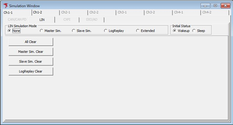
Figure 2: Clear operations for the selected Ch in None mode.
| Item | Description |
|---|---|
| All Clear button | Clears all simulation settings for the selected channel. |
| Master Sim. Clear button | Clears all master simulation settings for the selected channel. |
| Slave Sim. Clear button | Clears all slave simulation settings for the selected channel. |
| LogReplay Clear button | Clears all log replay settings for the selected channel. |
Master Simulation Mode
Master Sim. displays schedule and interrupt transmission settings. Figure 3 shows SensorSchedule selected. The four Frame List rows have Dir Tx, ID 10 (hexadecimal 0x10), and Delay 10000 ms, with D1 and D2 set to 18 01 → 22 01 → 1C 01 → 18 01 in that order.
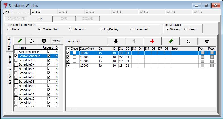
Figure 3: Example Master Sim. schedule settings.
For schedule and interrupt transmission operations, see Master Simulation. To use Catalog definitions, see Importing into Transmission Settings.
Slave Simulation Mode
Slave Sim. configures responses to headers received from the master. The Response ID List in Figure 4 is set to Available ID, with response data D1 1E and D2 01 for ID 10 (0x10).
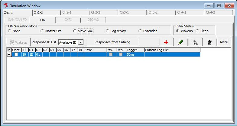
Figure 4: Example Slave Sim. response settings.
For per-ID settings and response operations, see Slave Simulation. To use definitions, see Responses from Catalog.
Log Replay Mode
In LogReplay, specify a communication log CSV in Log File and click Load. Figure 5 shows no Log File specified and an empty replay list. Loop is OFF, First Delay is 0 ms, Event Trigger is None, and Initial Status is grayed out.
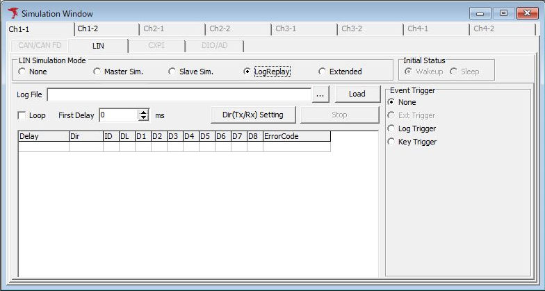
Figure 5: LogReplay settings before loading a log file.
For loading logs, transmission directions, and start conditions, see Log Replay.