Product Configuration and Functional Overview
Product Configuration
Use this product with the following components.
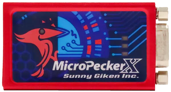
MicroPeckerX CAN FD Analyzer
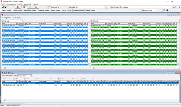
MicroPeckerX Control Software (GUI application)
Download from the Sunny Giken website
CAN Cables
Use the following CAN cables as needed.

S810-MX-CB1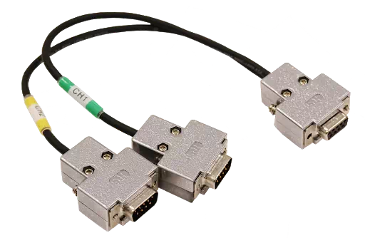
S810-MX-CB2Functional Overview
This product provides the following functions.
MicroPeckerX CAN FD Analyzer
| Function | Overview |
|---|---|
| Monitoring | Real-time monitoring of frame data on the connected CAN bus. - Start/stop logging control by trigger detection - Output frame filtering - Labeling/highlighting for specific frames - Fixed monitor display for same ID |
| Simulation | Various transmission modes are available. 1. Slot Transmission - Register up to 28 frames + immediate transmission of arbitrary frames - Periodic / Event / Event Periodic / Direct transmission 2. Log Replay mode 3. Burst Transfer mode |
| Analyze | Supports log data loading and analysis. - Automatic/manual log loading - Data search - Filter display - Channel log merge - Frame cycle measurement - GW frame delay measurement - GW frame loss measurement - GW frame retention measurement |
System Configuration Diagram
Example System Configuration
An example system configuration is shown below.
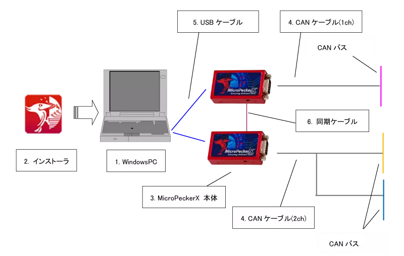
| No. | Device | Notes |
|---|---|---|
| 1 | Windows PC | Windows PC that runs the GUI application used to configure CAN monitor conditions and display CAN monitor data. |
| 2 | Installer | Required for initial installation and version upgrade of software (GUI application, USB driver). |
| 3 | MicroPeckerX main unit | Connect to PC via USB cable and to CAN bus via CAN cable. If using multiple MicroPeckerX units, connect them with sync cables. |
| 4 | CAN cable | Cable to connect MicroPeckerX to CAN bus. Available as 1ch cable (CB1) and 2ch cable (CB2). |
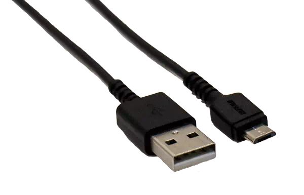
| 5 | USB cable | USB2.0 Micro-B cable for connection to PC. |
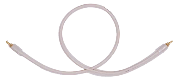
| 6 | Sync cable | Cable for synchronization of multiple MicroPeckerX units. |
Operating Environment
The required PC environment for configuration software is as follows.
| Item | Requirement |
|---|---|
| OS | Windows 11 (64bit), Windows 10 (64bit), Windows 8.1 (64bit) [*1] [*2] |
| CPU | Intel or AMD x86 processor (Core i5 / Ryzen 5 or higher recommended) |
| Hard Disk | 10 GB or more free space [*3] |
| Memory | 8 GB or more recommended |
| USB Port | USB2.0 (Hi-Speed), with enough ports for the number of connected MicroPeckerX units [*4] |
| Display | 1920 x 1080 or higher recommended |
| Other | Monitor, keyboard, mouse |
[*1]: On PCs with power-saving features, configure settings so that sleep, HDD stop, and CPU clock reduction do not occur while using this product.
[*2]: Operation in virtual environments is not supported.
[*3]: For long-duration monitoring, ensure sufficient hard-disk free space.
[*4]: When using an external USB hub, use a self-powered device and connect it with external power supplied.
(If a bus-powered USB hub is used, operation may fail or become unstable.)
Terms
The terms used in this document are described below.
| Term | Description |
|---|---|
| CAN | Abbreviation for Controller Area Network. Communication protocol developed for in-vehicle networks. International standard defined by ISO 11898. |
| CAN FD | Abbreviation for CAN with Flexible Data-rate. Extended CAN protocol enabling higher speed and larger data transfer. Standardized as ISO 11898-1:2015. |
| MicroPeckerX | Generic name for hardware systems with in-vehicle communication interfaces. Used together with applications for data capture and analysis. |
| Arbitration | Identifier (ID) field at the beginning of a CAN frame. When multiple nodes request transmission simultaneously, ID priority controls bus access. |
| Payload | Data field in a CAN frame. Stores raw data (signal values), up to 8 bytes (CAN) or 64 bytes (CAN FD). |
| Ch | Abbreviation for Channel. Physical or logical communication path of a CAN bus. MicroPeckerX can use multiple channels (for example, Ch1-1, Ch1-2) and transmit/receive independently on each. |
| GW | Abbreviation for Gateway. Device or software that relays data between networks with different communication protocols. |
| Monitoring | Real-time display of data captured from CAN bus in the GUI application. |
| Logging | Automatic saving of CAN bus data to a specified PC folder in text file (.csv) format. |
| Physical Value | Data value used as an actual value. Calculated as signal value * resolution + offset or (signal value + offset) * resolution. |
| Signal Value | Unconverted raw data value stored in payload of a CAN/CAN FD frame. |
| Log Replay | Function that reproduces/replays captured log file content. |
| Burst Transfer | Function that continuously transmits single frames or logs to create heavy CAN-bus load. |