Choosing a Simulation Mode and Basic Operations
| Task | Start Here |
|---|---|
| Create transmission settings from DBC or manually created frame definitions | Configure transmission frames from Catalog |
| Enter HEX or other data directly for periodic/event transmission | Send Frame, Event Transmission |
| Retransmit the original communication log onto the bus | Log Replay |
| Transmit frames or logs continuously | Burst Transmit |
Registering definitions and applying them to transmission slots are separate from starting operation. Check the connected target and transmission conditions, and follow the safety precautions.
For creating transmission settings from communication definitions and editing initial values in Physical/Logical/Raw formats, see Configuring Transmission Frames from Catalog. For verification using signal values in captured logs, see Signal Analysis.
Functional Overview
The simulation features of MicroPeckerX CAN FD Analyzer provide flexible control over transmission onto the CAN bus using the following modes. Configure these settings in Simulation Window.
| Feature | Description |
|---|---|
| Simulation mode selection | None (monitoring only) / Send Frame (slot transmission) / Log Replay (log replay) / Burst Transmit (burst transmission) / Extended (plug-in extensions) |
| Slot transmission (Send Frame) | Automatically transmits frames under various conditions using up to 28 slots • Periodic (periodic transmission) • Periodic Trigger (event-triggered periodic transmission) • Event (event-triggered transmission) • Event Periodic (event periodic transmission) |
| Direct transmission (Direct Transmit) | Use Direct Transmit in Send Frame to transmit a configured frame immediately with the Send button. Suitable for testing and manual operation. |
| Log replay (Log Replay) | Loads eligible CAN/CAN FD frames from a communication log CSV and transmits them according to replay settings (up to 3 million records; errors excluded) • Loop playback • Offset and repeat interval settings • Trigger-based start also available |
| Burst transmission (Burst Transmit) | Continuously transmits a single frame or eligible frames loaded from a log (up to 3 million records) • Loop/offset/trigger control |
| Trigger integration | Starts transmission in Send Frame / Log Replay / BurstTransmit using supported conditions such as Receive Trigger, Log Trigger, or Key Trigger |
| Detailed settings | Fine-tune parameters such as CAN/CAN FD, frame ID, DLC, data, increment settings, transmission count, and intervals |
These options make it easy to reproduce real-world frame transmission, test bus loads, recreate scenarios, and perform manual debugging with a variety of patterns.
Basic Operations (Periodic Transmission Frame Example)
Follow the steps below to configure a periodic transmission frame.
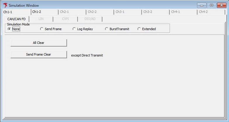
- Open Simulation Window
Select Simulation Window from the menu or toolbar.
- Select Send Frame mode
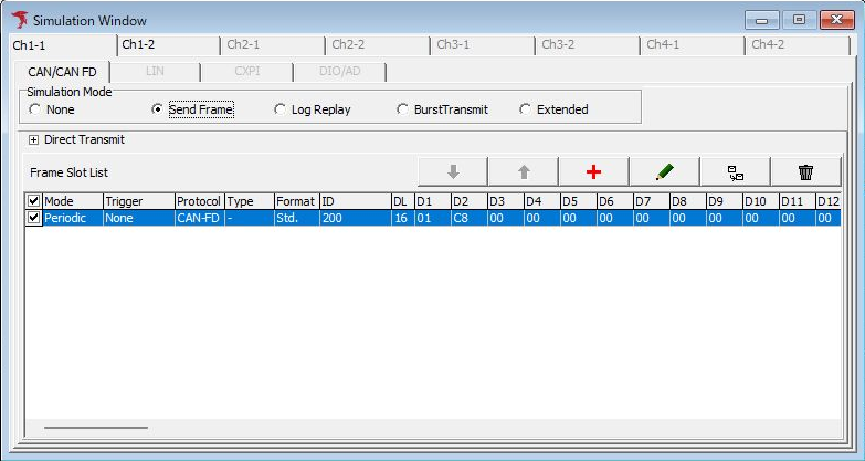
Click Send Frame in the Simulation Mode area.
- Open the CAN/CAN-FD Frame Setting dialog
Click the button in Simulation Window to open the CAN/CAN-FD Frame Setting dialog.
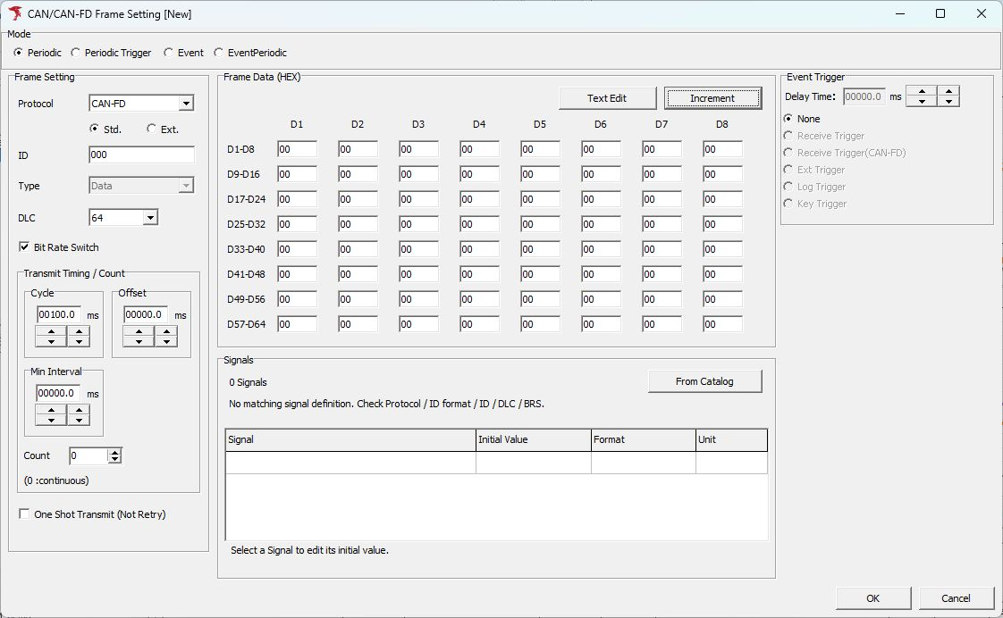
The figure shows ID 000 and 64 bytes immediately after adding a new slot. Enter the transmission conditions in the next step. For details on each option, see Configuring Slots.
- Configure periodic transmission
Configure periodic transmission in the CAN/CAN-FD Frame Setting dialog.
The following is an example of the minimum required settings.
| Item | Description | Example Setting |
|---|---|---|
| Mode | Select the transmission mode | Periodic (periodic transmission) |
| Protocol | Select CAN or CAN-FD | CAN-FD |
| ID | Enter the CAN ID | 100 |
| DLC | Select the DLC from the drop-down list | 64 |
| Cycle | Enter the transmission cycle | 100ms |
- Set the data
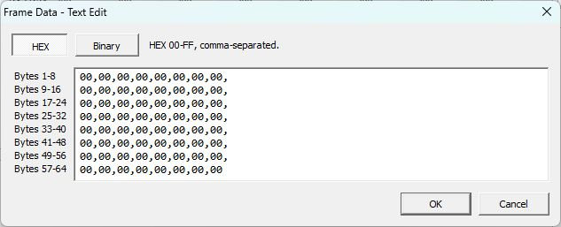
Enter transmission data in Frame Data (HEX) in the CAN/CAN-FD Frame Setting dialog. To enter all bytes together, click Text Edit. After entering the data, click OK to apply it to the parent dialog. For details, see Configuring Transmission Data.
The figure below shows 64 bytes of transmission data being edited together in HEX.
- Close the dialog
Click OK in the CAN/CAN-FD Frame Setting dialog to confirm the slot configuration. The configured frame appears in Frame Slot List in Simulation Window.
The figure of the list shows a different example, FanCommand_CH1 (ID 200, 16 bytes). For the settings in this procedure, verify that the ID is 100 and the data length is 64 bytes.
Select the leftmost checkbox for each frame to transmit. Starting monitoring with a frame checked starts transmission of that frame.
You can also toggle the checkboxes during monitoring. Unchecked frames are not transmitted.
- Start monitoring
Start monitoring by selecting Command → Start from the menu bar, clicking the button on the toolbar, or pressing F5. Frames are then transmitted.

Simulation Window Reference
Configure CAN simulation features in Simulation Window.
| Control | Description |
|---|---|
| CH selection tabs | Select the CH to use. |
| Simulation Mode | Select the Simulation Mode to use. - None: Monitor mode (no transmission) - Send Frame: Simulation mode - Log Replay: Log replay mode - BurstTransmit: Burst transmission mode - Extended: Extended mode |
| Settings area | Area for configuring transmission data and other settings. Its contents depend on the selected Simulation Mode. |
Monitor Mode
Select None for Simulation Mode in Simulation Window to use monitor mode without transmission.
In this mode, you can clear the settings for the selected CH.
| Control | Description |
|---|---|
| All Clear button | Click to clear all simulation settings for the selected channel. |
| Send Frame Clear button | Click to clear all Send Frame settings for the selected channel. Direct Transmit settings are not cleared. |