Device Connection Method
Connecting and Disconnecting Devices
This chapter explains the procedures for connecting and disconnecting devices.
How to Connect Devices
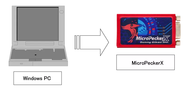
Connect MicroPeckerX to a Windows PC
Use the included USB cable to connect MicroPeckerX to a USB port on the PC.
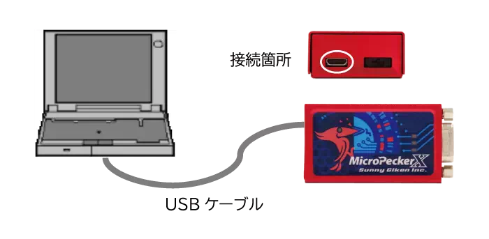
Note: Only the left USB port is available. Do not remove the cap on the right side.
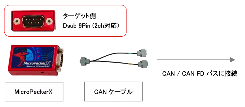
Connect to the Target
Use a CAN cable to connect MicroPeckerX to the CAN / CAN FD bus. Connections to CAN Hi, CAN Lo, and GND are required.
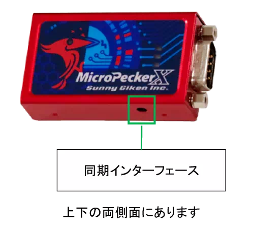
Connect Synchronization Cable
When synchronizing multiple MicroPeckerX units, connect them with the synchronization cable included with this product.
Connection Example for 3 Units
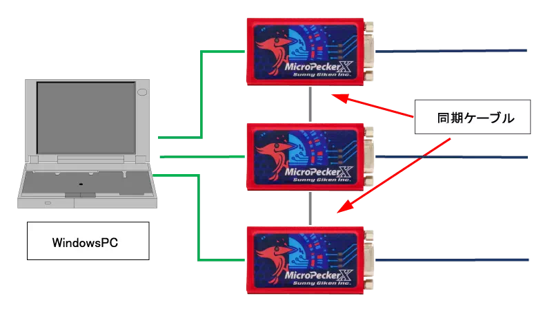
Note: Connect/disconnect synchronization cables only while monitoring is stopped.
Switching Termination Resistor
ON/OFF switching of the termination resistor can be configured in the GUI application.
How to Disconnect Devices
The procedure for disconnecting devices is described below.
Disconnect MicroPeckerX from Windows PC
Unplug MicroPeckerX from the Windows PC.
D-sub Connector Details
D-sub pin assignments are as follows.
MicroPeckerX Main Unit S810-MX-FD2
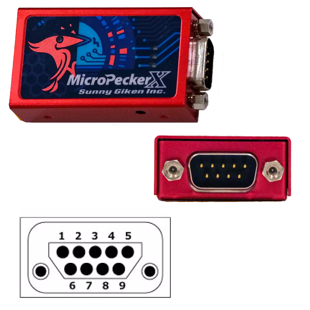
| Pin | Function |
|---|---|
| 1 | CAN Lo(CH1) |
| 2 | CAN Lo(CH0) |
| 3 | GND |
| 4 | Not Connected. |
| 5 | Not Connected. |
| 6 | GND |
| 7 | CAN Hi(CH0) |
| 8 | CAN Hi(CH1) |
| 9 | Not Connected. |
CAN 1ch Clip Cable S810-MX-CB1
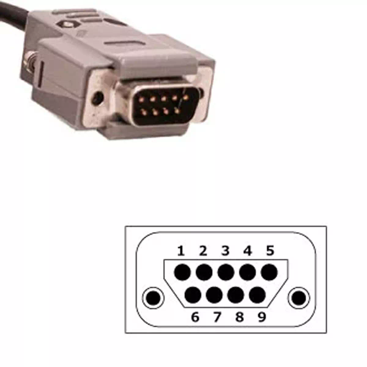
| Pin | Function |
|---|---|
| 1 | Not Connected. |
| 2 | CAN Lo |
| 3 | GND |
| 4 | Not Connected. |
| 5 | Not Connected. |
| 6 | Not Connected. |
| 7 | CAN Hi |
| 8 | Not Connected. |
| 9 | Not Connected. |
CAN 2ch D-sub Cable S810-MX-CB2 (Ch1/Ch2 connector side)
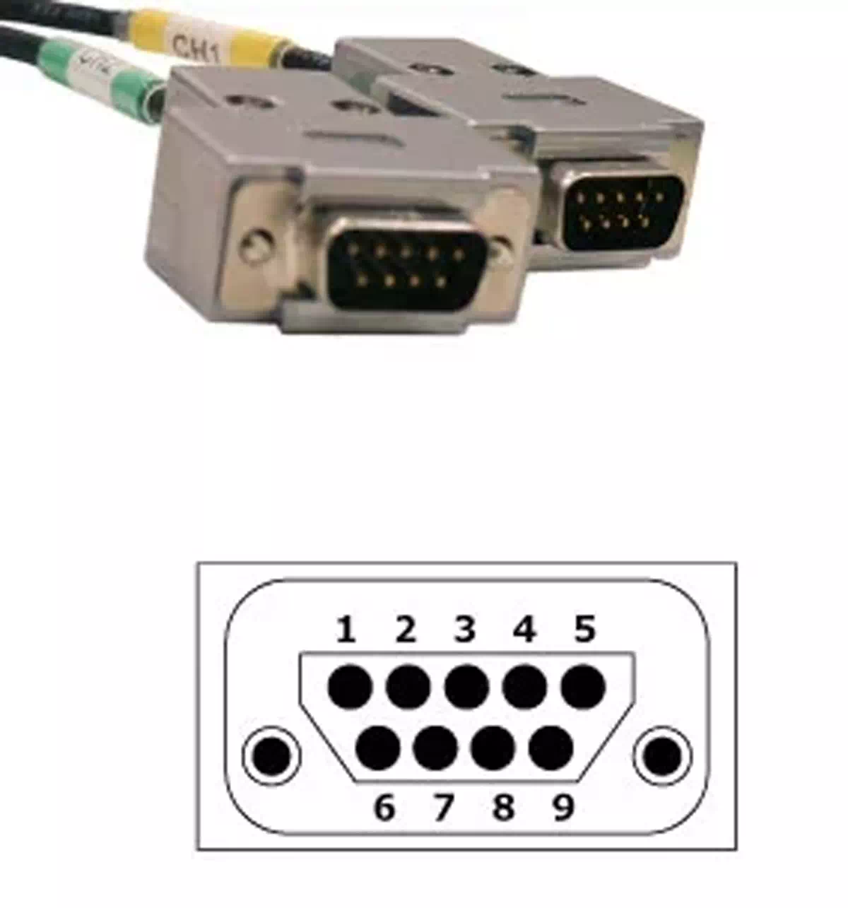
| Pin | Function |
|---|---|
| 1 | Not Connected. |
| 2 | CAN Lo |
| 3 | GND |
| 4 | Not Connected. |
| 5 | Not Connected. |
| 6 | Not Connected. |
| 7 | CAN Hi |
| 8 | Not Connected. |
| 9 | Not Connected. |
Note: The 2-channel connector is split into individual 1-channel lines.
Incorrect wiring may damage both MicroPeckerX and the target device.