Slot Transmission
The slot transmission function supports transmission under various conditions such as periodic transmission and event transmission.
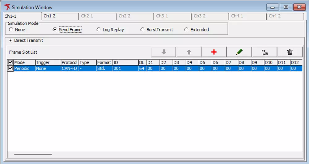
Select Send Frame in Simulation Mode of the Simulation Window to use this function.
Send Frame Screen Description
| Screen Menu | Description |
|---|---|
| Frame Slot List | Displays configured slot information (note1) |
 button button | Adds a slot setting. Clicking opens the CAN/CAN-FD Frame Setting dialog. |
 button button | Edits the selected slot setting. Clicking opens the CAN/CAN-FD Frame Setting dialog. (note2) |
 button button | Copies configuration of the selected slot. (note3) |
 button button | Deletes the selected slot. |
 button button | Moves the selected slot. (note4) |
note1: Maximum configurable slots: 28.
note2: You can also edit a slot by double-clicking anywhere except the slot checkbox in the list.
note3: You can also copy a slot by right-drag-and-drop of the target slot in the list.
note4: You can also move a slot by drag-and-drop of the target slot in the list.
Slot Configuration
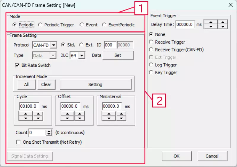
In Send Frame mode, clicking the + button or editing the selected slot opens the CAN/CAN-FD Frame Setting dialog.
You can configure transmission frames in this dialog.
The following describes configuration items for Mode (transmission mode) and Frame Setting (transmission frame).
CAN/CAN-FD Frame Setting Dialog (Mode, Frame Setting)
| No. | Item | Detail | Description |
|---|---|---|---|
| 1 | Mode | Periodic | Specifies periodic transmission for the target frame. |
| Periodic Trigger | Specifies a frame that starts periodic transmission when a trigger condition occurs. Used together with the event trigger function. | ||
| Event | Specifies event transmission for the target frame. Used together with the event trigger function. | ||
| EventPeriodic | Specifies event periodic transmission for the target frame. Used together with the event trigger function. | ||
| 2 | Frame Setting | Protocol | Set to CAN or CAN FD. Select from: - CAN - CAN-FD |
| Std./Ext. | Set Standard ID (Std) or Extended ID (Ext). | ||
| ID | Set CAN ID (hex). | ||
| Type | Set Data or Remote frame. Selectable only when Protocol is CAN. Disabled when CAN-FD is selected. | ||
| DLC | Set DLC. Select from: - When Protocol = CAN: 0,1,2,3,4,5,6,7,8,9,10,11,12,13,14,15 - When Protocol = CAN-FD: 0,1,2,3,4,5,6,7,8,12,16,20,24,32,48,64 | ||
| Data Set button | Set frame data. Clicking Set opens the Data Setting dialog. | ||
| Bit Rate Switch | Configurable only for CAN FD frames. - Checked: Enables baud rate setting for CAN FD data field configured in Device Window. - Unchecked: Disables it (all parts use arbitration baud rate). | ||
| Increment Mode | Data can be incremented on each frame transmission. Increment target can be set ON/OFF by byte. - All button: sets all byte data as increment targets.- Clear button: excludes all byte data from increment targets.- Setting button: opens Increment Setting dialog for increment-target byte configuration. | ||
| Cycle | Set transmission cycle. Minimum unit is 0.1 ms (100 us). (note1) | ||
| Offset | Set offset time from simulation start to transmission start. Minimum unit is 0.1 ms (100 us). (note1)(note2) | ||
| Min.Interval | Set guaranteed minimum transmission interval. Minimum unit is 0.1 ms (100 us). (note1) | ||
| Count | Set number of transmissions for periodic/event periodic transmission. Setting 0 means unlimited. (note3) | ||
| One Shot Transmit | Set retransmission behavior on error detection. - Checked: no retransmission on error. - Unchecked: retransmission on error. | ||
| Signal Data Setting button | Clicking opens signal setting dialog.Signal setting is under development and unavailable. |
note1: You can also change the ones and tenths digits with  button.
note2: When Event or Event Periodic is selected, if an event is received before offset time elapses, event transmission is executed.
note3: Under the following conditions, periodic transmission count starts from event transmission.
- Mode:
EventPeriodic - Count set to a value other than 0
- Count transmissions completed
- Event detected
The dialog title bar changes depending on how the CAN Frame Setting dialog is opened.
| Operation | Title | Example |
|---|---|---|
| Add new slot | Adds [New] at the end |  |
| Edit existing slot | Adds [Slot number] at the end |  |
| Duplicate selected slot | Adds [Copy] at the end |  |
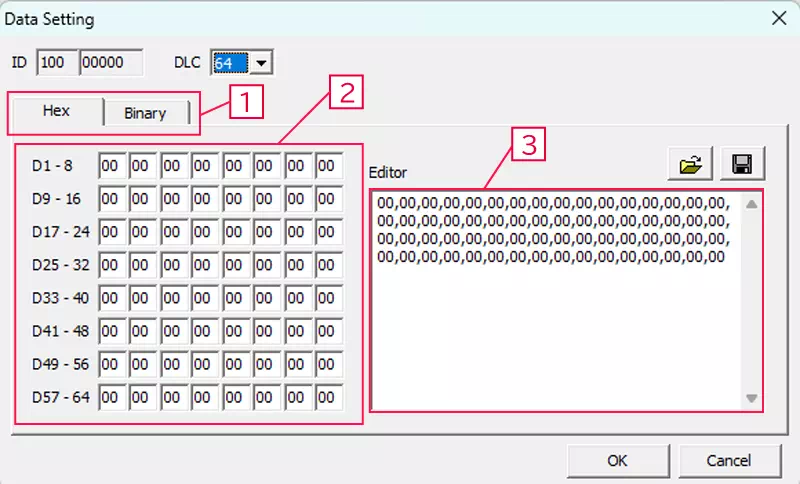
Data Setting Dialog
Click Data Set in CAN/CAN-FD Frame Setting to open the Data Setting dialog.
Use this dialog to configure transmission data.
| Item | Description | Notes |
|---|---|---|
| ID | CAN ID | Cannot be edited in Data Setting. |
| DLC | Data length | Display of data setting areas [2] and [3] changes according to DLC settings. |
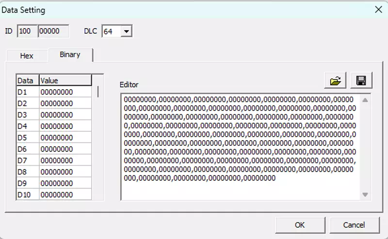
| [1] | Hex/Binary display tab | Switch data display between Hex and Binary. |
| [2] | Per-byte data setting area (note1) | Each cell represents 1 byte. Top-left cell is Data1. |
| [3] | Editor area (note1) | Data can be set as comma-separated bytes. Settings can be saved/loaded as CSV. |
 button button | Load Data Setting file | Loads CSV file saved from Data Setting. |
 button button | Save Data Setting file | Saves Data Setting content as CSV. Target is settings in [3]. |
note1: Data can be changed in either [2] or [3]. Both displays are synchronized.
Display Example in Binary Tab
Increment Setting Dialog
Click Setting in Increment Mode of CAN/CAN-FD Frame Setting to open the Increment Setting dialog.
In this dialog, you can specify increment-target data.
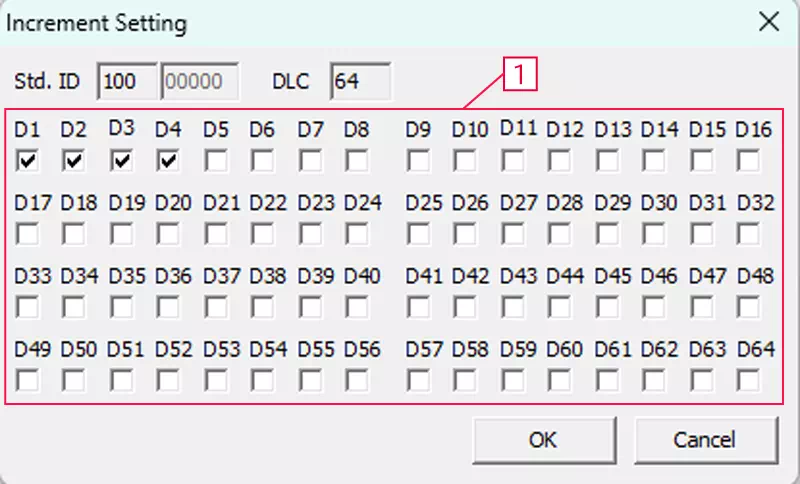
| Screen Menu | Description | Notes |
|---|---|---|
| ID | CAN ID | Cannot be edited in Increment Setting. |
| DLC | Data length | Cannot be edited in Increment Setting. |
| [1] | Increment target check | Configure whether each 1-byte data item is included as an increment target. |