Burst Transmission Function
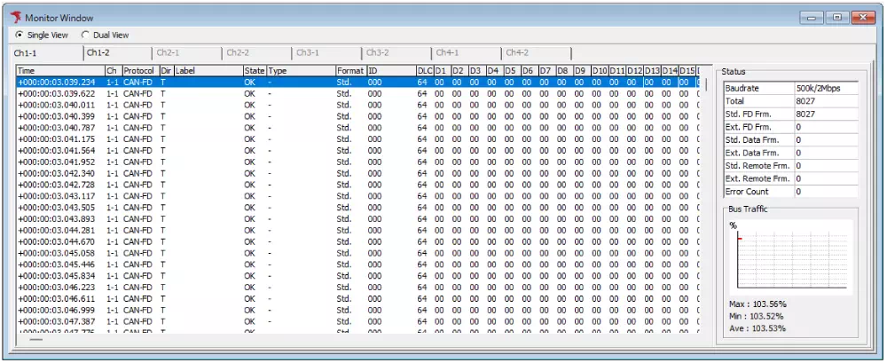
The burst transmission function creates a high-load CAN bus state by sending messages continuously without wait time.
It can be used to evaluate transmit/receive behavior under heavy bus load.
Product Usage Image
Burst transmission has the following two modes:
- 1Frame Mode: burst transmission of a single frame
- Log Mode: burst transmission using a log file
1Frame Mode
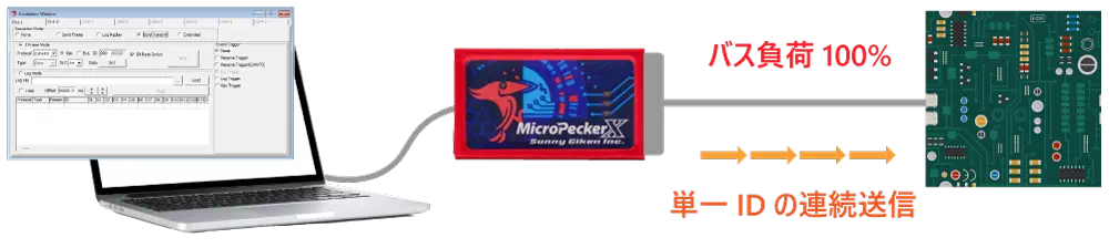
In 1Frame Mode, a single frame is transmitted continuously without wait time.
Because bus load can be raised close to 100%, it is useful for evaluating whether a target ECU can transmit/receive correctly under heavy load.
In 1Frame Mode, CAN ID and payload can be configured freely.
Log Mode
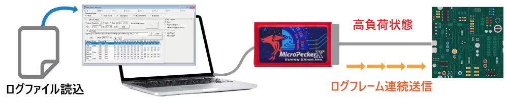
In Log Mode, frames in a log file are transmitted continuously without wait time.
By setting log frames to those expected by the target ECU, it can be used to evaluate continuous frame reception processing.
Basic Operation
This section explains the basic flow for using burst transmission. Here, 1-frame burst transmission is used.
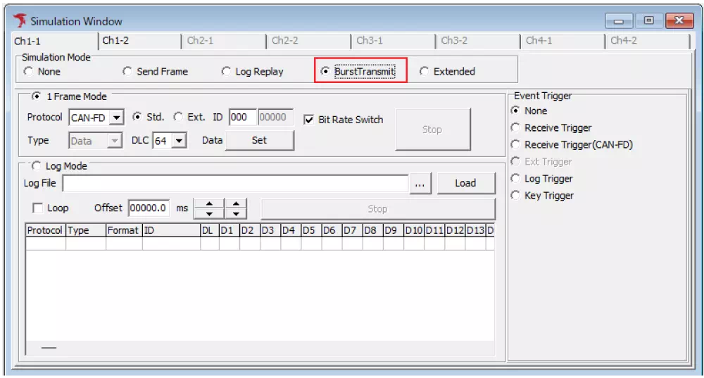
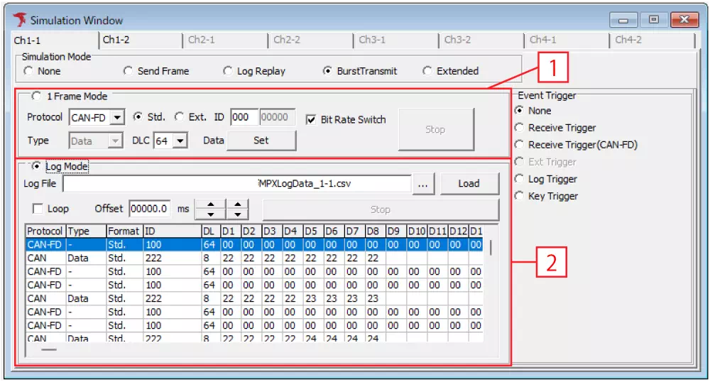
- Select BurstTransmit in Simulation Window
OpenSimulation Windowfrom menu or toolbar.
SelectBurstTransmitin Simulation Mode to display the burst transmission settings screen.
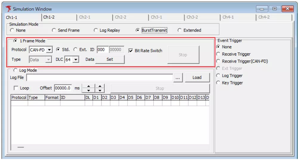
- Confirm 1 Frame Mode is selected
Confirm that1 Frame Moderadio button is selected.
By default, it is configured to continuously transmit a CAN FD frame with CAN ID000and DLC64 bytes.
- Start monitoring
After burst settings are configured, start monitoring to execute burst transmission.
SelectCommand -> Startin menu bar, or click toolbar button, or press
 F5.
BurstTransmit Screen Description
| No | Mode | Item | Description |
|---|---|---|---|
| 1 | 1 Frame Mode | protocol | Set to CAN or CAN FD. Select from dropdown. |
| Std./Ext | Set to standard ID (Std) or extended ID (Ext). | ||
| ID | Set CAN ID (Hex). | ||
| Type | Set Data or Remote frame. Selectable only when Protocol is CAN. When CAN-FD is selected, this item is read-only. | ||
| DLC | Set DLC from dropdown. - For CAN: 0,1,2,3,4,5,6,7,8,9,10,11,12,13,14,15 - For CAN-FD: 0,1,2,3,4,5,6,7,8,12,16,20,24,32,48,64 | ||
| Data Set button | Set frame data. Clicking Set opens Data Setting dialog. | ||
| Bit Rate Switch | Available when CAN FD frame is selected. - ON: enable data-phase baud rate configured in Device Window - OFF: disable data-phase baud rate and use arbitration-phase baud rate for all | ||
| Stop button | Stops burst transmission. | ||
| 2 | Log Mode | Log File | Shows path and file name of log file to be loaded. |
 button button | Opens file selection dialog to choose log file. Note: Selecting a file does not load it. Click Load to read data (note1). | ||
| Load button | Loads log file. | ||
| Loop | Sets whether log replay transmission is repeated. If unchecked, system enters wait state after all log data is sent. | ||
| Offset | Sets time from monitoring start to log replay start. When event trigger is set, this becomes time from event detection to replay start (note2). | ||
| Stop button | Stops log replay transmission while running. | ||
| Log data area | Displays loaded log file contents (note3). |
note1: MicroPecker Analyzer log files cannot be loaded.
note2:  can also be used to change 1s and 0.1s digits.
note3: In loaded log files, only data frames and remote frames are used; error records are ignored.
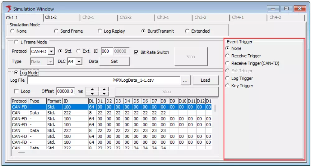
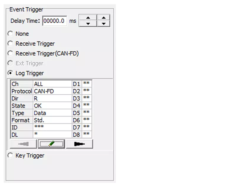
Event Trigger Settings
You can start burst transmission in response to event trigger detection.
| Item | Description |
|---|---|
| None | No event trigger is used. |
| Receive Trigger | Detects reception of specified CAN ID in CAN frame as event. |
| Receive Trigger(CAN-FD) | Detects reception of specified CAN ID in CAN FD frame as event. |
| Ext Trigger | Detects port input as event (note1). |
| Log Trigger | Detects specified monitoring log as event. |
| Key Trigger | Detects specified key input as event. |
note1: Ext Trigger is under development and not available.
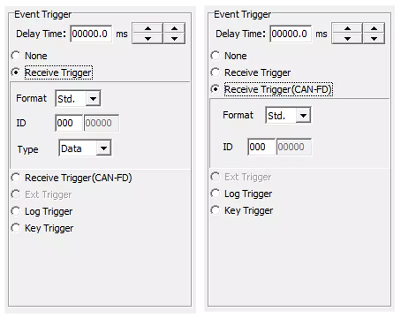
Receive Trigger / Receive Trigger(CAN-FD) settings
Selecting Receive Trigger allows configuration of target received CAN ID used as event trigger.
Example use: transmit frames when specific CAN ID is received.
When Receive Trigger is selected, setting area appears. Set target CAN ID of received frame.
| Item | Description |
|---|---|
| Format | Set standard ID (Std) / extended ID (Ext) |
| ID | Set trigger target CAN ID |
| Type | Set Data / Remote frame (CAN frames only) |
Log Trigger settings
Selecting Log Trigger allows configuration of log conditions used as events.
Detailed trigger conditions such as specific data and error frames can be set.
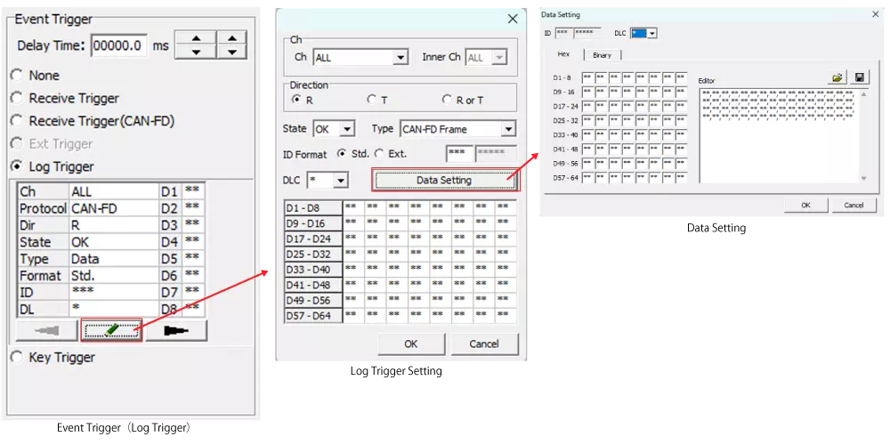
In Log Trigger, clicking  opens Log Trigger dialog. Clicking
 Data Setting opens Data Setting dialog.
Log Trigger screen description
| Menu | Description |
|---|---|
| Setting display area | Displays log information used as trigger. Double-click opens Log Trigger setting dialog. |
| button | Opens Log Trigger setting dialog. |
Log Trigger setting dialog
Set condition details of logs to detect as trigger.
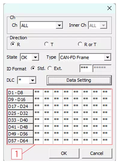
| Item | Description | Setting Values |
|---|---|---|
| Ch | Target Ch (per MicroPeckerX) | Select from ALL / 1 / 2 / 3 / 4 |
| InnerCh | Target internal Ch | Select from ALL / 1 / 2 |
| Direction | Target Tx/Rx direction | R / T / R or T |
| State | Normal or error frame | OK / NG |
| Type | Target frame type | Select by State:OK: CAN-FD Frame, CAN Data Frame, Remote FrameNG: All Error, Bus Error, Error Warning, Error Passive, Bus Off Entry, Bus Off Recovery, Overload, Bus Lock, Arbitration Lost, Stuff Error, Form Error, Ack Error, CRC Error, Recessive Bit Error, Dominant Bit Error, Ack Delimiter Error |
| ID Format | CAN ID specification | Select standard (Std.) or extended (Ext.). CAN ID is Hex. If * is entered, CAN ID is not checked. |
| DLC | CAN data length | If * is entered, DLC is not checked. |
| Data Setting button | Open Data Setting dialog | - |
| [1] | Data area | Shows data set in Data Setting dialog. |
Data Setting dialog
Clicking Data Setting in Log Trigger dialog opens Data Setting dialog.
It allows data-condition configuration of target logs. Display format can be switched between Hex and Binary tabs.
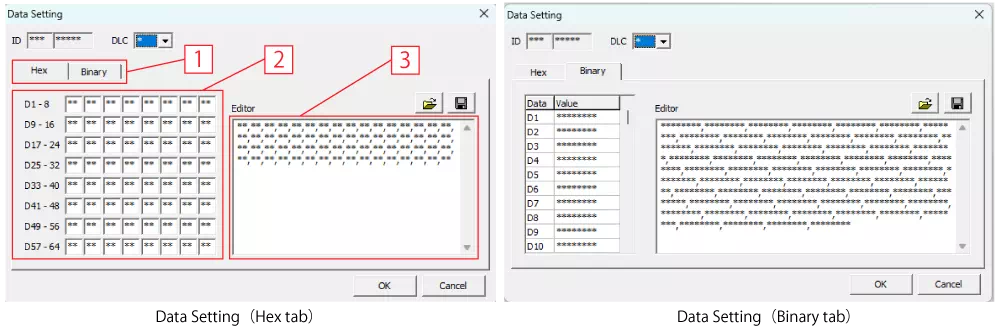
| Item | Description | Details |
|---|---|---|
| ID | CAN ID | CAN ID cannot be edited in Data Setting. |
| DLC | Data length | Data setting areas [2][3] change according to DLC setting. If * is entered, DLC is not checked. |
| [1] | Hex/Binary tab | Switches data display between Hex/Binary. |
| [2] | Per-byte setting area (note1) | Each cell represents 1 byte. Top-left cell is Data1. If * is entered, data is not checked. |
| [3] | Editor area (note1) | Data can be set in comma-separated byte format. If * is entered, data is not checked.Settings can be saved/loaded as CSV. |
 button button | Load Data Setting file | Loads CSV saved by Data Setting. |
 button button | Save Data Setting file | Saves Data Setting contents to CSV. Target is [3] settings. |
note1: Data can be edited in either [2] or [3]. Both are synchronized.
Key Trigger settings
Selecting Key Trigger allows keyboard input to be used as event trigger.
Example: transmit frames according to key input.
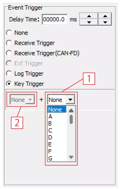
| Item | Description | Details |
|---|---|---|
| [1] | Main key | Sets trigger key. Available: 0-9, A-Z, F1-F12, Space |
| [2] | Sub key | Sets modifier key combined with main key. Available: Shift, Ctrl, Alt |