Hardware and Functional Specifications
MicroPeckerX Hardware Specifications
| Item | Specification |
|---|---|
| Power supply | USB bus power (5 V, 300 mA) |
| Dimensions | 65 (W) x 35 (D) x 16 (H) mm |
| Weight | 45 g |
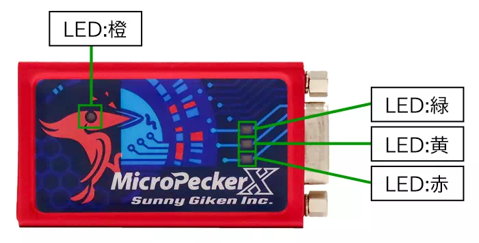
| LED | 4 LEDs Orange: Power status (ON when powered) Green: Communication Ch1 (blinks during CAN/CAN FD communication on Ch1*) Yellow: Communication Ch2 (blinks during CAN/CAN FD communication on Ch2*) Red: Error (ON when an error occurs) *Blinks on GW target ID RX/TX and cyclic transmission, except Immediate GW RX/TX. |
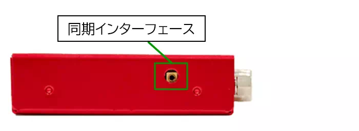
| Sync interface | 2 ports |
| CAN/CAN FD interface | DSub 9-pin, 2 channels |
| USB ports | 2 x USB Micro-B (main, sub) |
International Standards
- CE marking certified
EMI: EN55011 (2020) Group1 ClassB
EMS: EN61000-4-2 (2009), EN61000-4-3 (2010) - FCC compliant
This device complies with Part 15 of the FCC Rules. Operation is subject to the following two conditions:
(1) This device may not cause harmful interference, and (2) this device must accept any interference received, including interference that may cause undesired operation.
Front
Top/Bottom Side
Left/Right Side
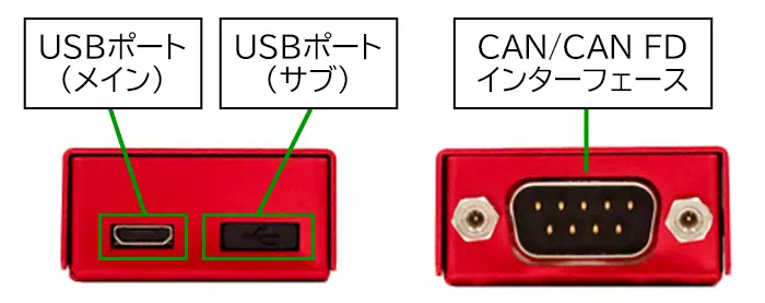
Do not use the USB sub port.
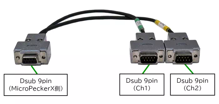
CAN 2ch DSub Cable Specifications
| Item | Specification |
|---|---|
| Signal | CAN-Hi, CAN-Lo, GND * Uses DSub 9-pin connector |
| Cable length | Total length: 0.3 m |
| Shield | Yes |
Connector Pins
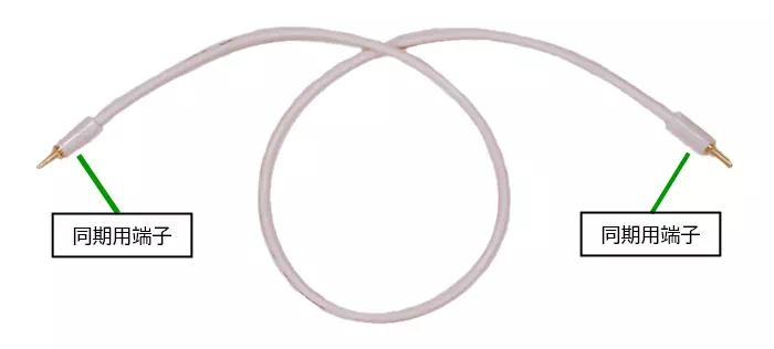
Sync Cable Specifications
| Item | Specification |
|---|---|
| Cable length | Total length: 25 cm |
| Shield | No |
The sync cable is not used in this system.
MicroPeckerX InstaGW Functional Specifications
| Item | Details | |
|---|---|---|
| CAN/CAN FD interface | 2 channels | |
| Per-channel settings | Protocol | Selectable: CAN / CAN FD |
| Communication baud rate: arbitration phase | 4 selectable values: 125 kbps / 250 kbps / 500 kbps / 1 Mbps | |
| Communication baud rate: data phase | 5 selectable values: 500 kbps / 1 Mbps / 2 Mbps / 4 Mbps / 5 Mbps *If arbitration phase is 125 kbps, data phase is corrected to 500 kbps. | |
| Sample point | 6 selectable values: 60% / 65% / 70% / 75% / 80% / 85% *If data phase is set to 5 Mbps, sample point is corrected to 75%. | |
| Termination resistor | Selectable: enabled / disabled | |
| Gateway function (common) | Gateway routing channel | Selectable per ID: CH1->CH2 or CH2->CH1 |
| ID type | Selectable: standard ID / extended ID | |
| Signal gateway | Not supported | |
| Immediate gateway | Max configurable IDs | Up to 32 total (CH1->CH2 and CH2->CH1 combined) |
| Target ID and DL | Wildcard supported | |
| Gateway latency | Approx. 3.5 us [*1] | |
| Standard gateway | Max configurable IDs | Up to 64 total (CH1->CH2 and CH2->CH1 combined) |
| Target ID and DL | Individual configuration required | |
| ID replacement | Configurable to any ID for CH1->CH2 and CH2->CH1 | |
| Transmit delay setting | Configurable range: 0 to 65535 ms (1 ms step) | |
| Gateway latency | Approx. 12.5 to 20 us (depends on data length) [*1] | |
| Cyclic transmission | Transmit channel selection | CH1 / CH2 selectable per ID |
| ID type | Selectable: standard ID / extended ID | |
| Number of configurable frames | Up to 32 total (CH1 + CH2) | |
| Transmission timing resolution | 1 ms | |
| Frame type | Cyclic transmission | |
| Transmission cycle | Configurable range: 1 to 65535 ms (1 ms step) | |
| Initial transmission offset | Configurable range: 0 to 65535 ms (1 ms step) | |
| Transmission count | Not configurable | |
| Minimum guaranteed interval for same frame | Not supported | |
| Communication log output | Not supported | |
| Save/load settings | Saved in Excel format | |
| Maximum continuous operation time | Up to 49 days and 17 hours | |
[*1]: Measured under CAN FD communication (arbitration phase 500 kbps, data phase 2 Mbps).