Device Connection Method
During GW Configuration Using a PC
Use the included USB cable to connect MicroPeckerX to a USB port on your PC.
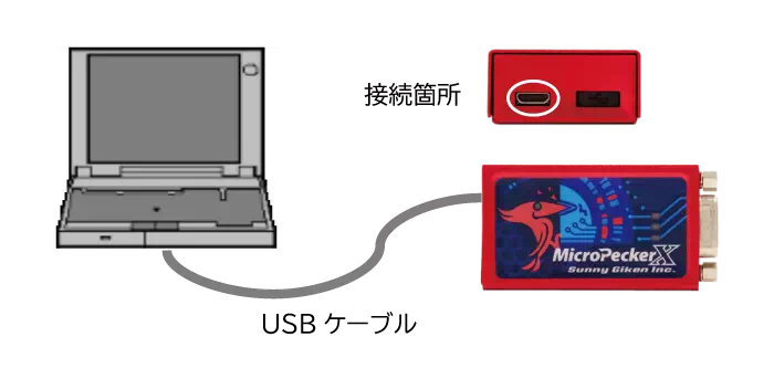
Only the left USB port can be used. Do not remove the cap on the right side.
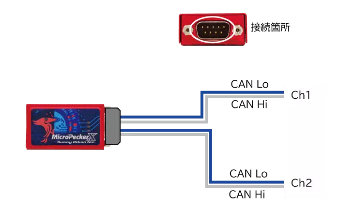
During GW Operation
According to the DSub pin assignment, connect power, CAN Hi/CAN Lo for each channel, and GND.
DSub Connector Details
DSub pin assignments are as follows.
MicroPeckerX Main Unit
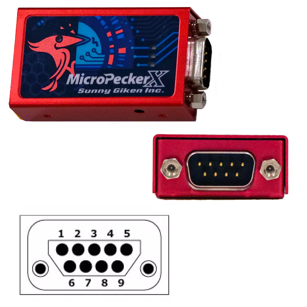
| Pin | Function |
|---|---|
| 1 | CAN Lo(CH1) |
| 2 | CAN Lo(CH0) |
| 3 | GND |
| 4 | Not Connected. |
| 5 | Not Connected. |
| 6 | GND |
| 7 | CAN Hi(CH0) |
| 8 | CAN Hi(CH1) |
| 9 | Not Connected. |
CAN 2ch Dsub Cable (Ch1 and Ch2 Connector Side)
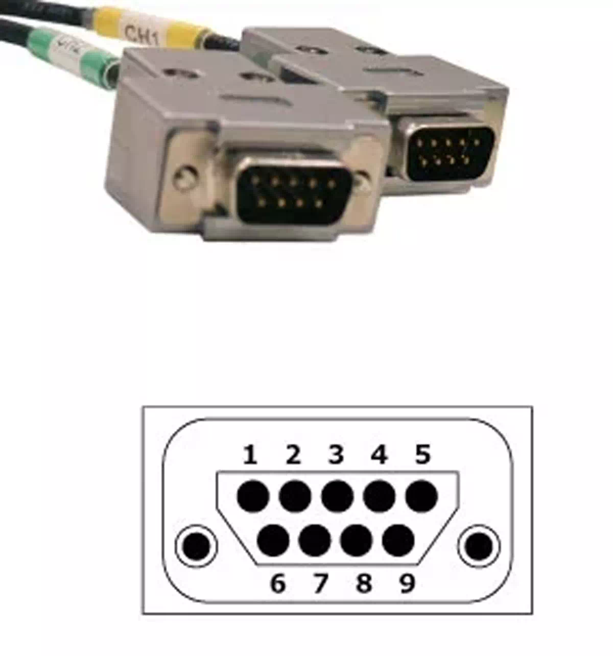
| Pin | Function |
|---|---|
| 1 | Not Connected. |
| 2 | CAN Lo |
| 3 | GND |
| 4 | Not Connected. |
| 5 | Not Connected. |
| 6 | Not Connected. |
| 7 | CAN Hi |
| 8 | Not Connected. |
| 9 | Not Connected. |
* The 2-channel connector is split into each 1-channel connection.