GW Setting File Specification and Sheet Descriptions
This product uses an Excel-format GW setting file to configure MicroPeckerX InstaGW. This section explains the file specification and configuration items.
The GW setting file template (ConfigTemplate.xlsx) is included in the MicroPeckerX InstaGW package folder.
Copy the template to any folder before use.
GW Setting File Specification
Sheet Order
The Excel sheets must be in this order:
Com -> Immediate GW -> Gateway -> Periodic Frame
You may add additional sheets after these.

Com Sheet
The Com sheet defines communication settings. This sheet is required.
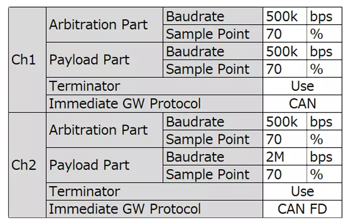
| Item | Description | Setting Values | |
|---|---|---|---|
| Arbitration Part | Baudrate | Baud rate for arbitration part | Select from: 125k, 250k, 500k, 1M |
| Sample Point | Sample point for arbitration part | Select from: 60%, 65%, 70%, 75%, 80%, 85% | |
| Payload Part | Baudrate | Baud rate for payload part | Select from: 500k, 1M, 2M, 4M, 5M |
| Sample Point | Sample point for payload part | Select from: 60%, 65%, 70%, 75%, 80%, 85% | |
| Terminator | Termination resistor usage | Select from: Use, Not Use | |
| Immediate Gateway Protocol | Transmit protocol used by Immediate GW | Select from: CAN, CAN FD | |
If the loaded file has the following arbitration/payload baud rate combinations, payload baud rate is automatically corrected.
| Arbitration Baud Rate | Payload Baud Rate | |
|---|---|---|
| Before Correction | After Correction | |
| 125 kbps | 1 Mbps, 2 Mbps, 4 Mbps, 5 Mbps | 500 kbps |
| 250 kbps | 4 Mbps, 5 Mbps | 2 Mbps |
| 1 Mbps | 500 kbps | 1 Mbps |
If the loaded file has the following payload baud rate/sample point combinations, payload sample point is automatically corrected.
| Payload Baud Rate | Payload Sample Point | |
|---|---|---|
| Before Correction | After Correction | |
| 2 Mbps, 4 Mbps | 65%, 75%, 85% | -5% from the original (60%, 70%, 80%) |
| 5 Mbps | 60%, 65%, 70%, 80%, 85% | 75% |
Immediate GW Sheet
The Immediate GW sheet configures immediate gateway rules.
Immediate GW uses hardware processing in MicroPeckerX, enabling very low latency gateway behavior.
You can configure up to 32 IDs total for CH1->CH2 and CH2->CH1.
When a frame with a target ID is received, a frame with the same ID is sent on the opposite channel using the configured protocol and DL.
Wildcard (*) is supported for GW target ID and DL.
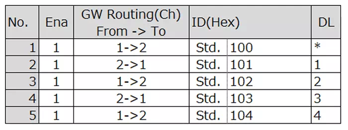
| Item | Description | Setting Values |
|---|---|---|
| Ena | Enable/disable this entry | Select from: 0 (disabled), 1 (enabled) |
| GW Routing(Ch) From -> To | GW transfer direction (channel) | Select from: 1->2, 2->1 |
| ID(Hex) | Target GW ID | Enter value (right side) in hexadecimal. Select format (left side): Std. (standard ID), Ext. (extended ID) |
| DL | Target GW DL | Select from: *, 1, 2, 3, 4, 5, 6, 7, 8, 12, 16, 20, 24, 32, 48, 64 |
In Immediate GW, destination protocol (CAN/CAN FD) follows Immediate Gateway Protocol in communication settings.
If destination protocol is CAN, data length is handled as follows:
| Source Protocol | Data Length |
|---|---|
| CAN | Unchanged |
| CAN FD | Up to 8 bytes (from the start) |
In Immediate GW, CAN FD frames from error-passive nodes (ESI = 1) are gatewayed. (They are filtered in standard GW.)
Gateway Sheet
The Gateway sheet configures standard gateway rules.
Standard GW uses software processing in MicroPeckerX. It supports:
- transmission timing offset,
- different source/destination IDs (ID conversion).
You can configure up to 64 IDs total for CH1->CH2 and CH2->CH1.
When a frame with a target source ID is received, a destination frame with configured protocol/ID/DL is transmitted at the configured timing.
| Item | Description | Setting Values | |
|---|---|---|---|
| Ena | Enable/disable this entry | Select from: 0 (disabled), 1 (enabled) | |
| GW Routing(Ch) From -> To | GW transfer direction (channel) | Select from: 1->2, 2->1 | |
| GW From | Protocol | Source protocol | Select from: CAN, CAN FD |
| ID(Hex) | Source ID | Enter value (right side) in hexadecimal. Select format (left side): Std. / Ext. | |
| DL | Source DL | Select from: 1, 2, 3, 4, 5, 6, 7, 8, 12, 16, 20, 24, 32, 48, 64 | |
| GW To | Protocol | Destination protocol | Select from: CAN, CAN FD |
| ID(Hex) | Destination ID | Enter value (right side) in hexadecimal. Select format (left side): Std. / Ext. | |
| DL | Destination DL (*) | Select from: 1, 2, 3, 4, 5, 6, 7, 8, 12, 16, 20, 24, 32, 48, 64 | |
| Delay(ms) | Delay from source receive to destination transmit | Enter decimal integer (unit: ms) | |
If destination DL is shorter than source DL, excess data is truncated. (Example: source DL=8, destination DL=5 -> bytes after D5 are truncated.)
Periodic Frame Sheet
The Periodic Frame sheet configures cyclic transmission.
MicroPeckerX InstaGW can cyclically transmit frame data to any channel. It can also be used together with GW processing, so each channel can be used as a standalone simulation node.
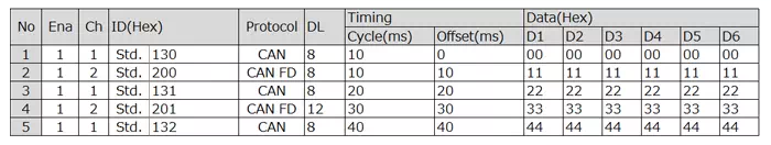
| Item | Description | Setting Values | |
|---|---|---|---|
| Ena | Enable/disable this entry | Select from: 0 (disabled), 1 (enabled) | |
| Ch | Transmit channel | Select from: 1 (CH1), 2 (CH2) | |
| ID(Hex) | Transmit ID | Enter value (right side) in hexadecimal. Select format (left side): Std. / Ext. | |
| Protocol | Transmit protocol | Select from: CAN, CAN FD | |
| DL | Transmit DL | Select from: 1, 2, 3, 4, 5, 6, 7, 8, 12, 16, 20, 24, 32, 48, 64 | |
| Timing | Cycle(ms) | Transmission cycle | Enter decimal integer (unit: ms) |
| Offset(ms) | Transmission offset | Enter decimal integer (unit: ms) | |
| Data(Hex) | D1 to D64 | Transmit data (*) | Hex input |
Data beyond transmit DL does not need to be entered. (Example: if DL=8, D9 and later are unnecessary.)