DIO Input/Output Settings
In DIO simulation, you can configure DIO input/output settings.
Basic Operation
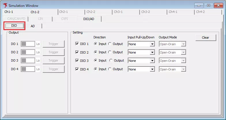
- Select DIO in Simulation Window
SelectSimulation Windowfrom menu/toolbar, then selectDIOin protocol tab.
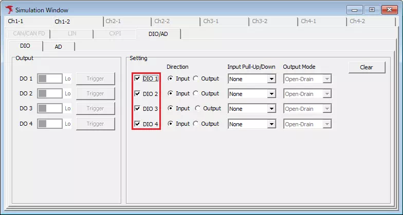
- Enable/disable DIO
Use checkboxes on the left of DIO1 to DIO4. ON = enabled, OFF = disabled.
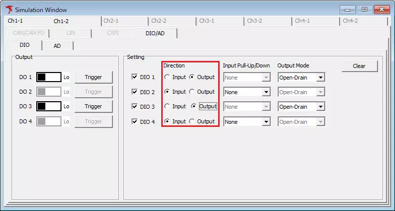
- Select input/output direction
UseDirectionradio buttons. SelectInputfor monitoring level,Outputfor controlling output.
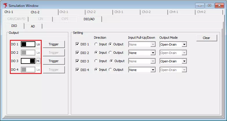
- Select output level
IfOutputis selected in step 3, use toggle switches on the right of DO1 to DO4.
- Start monitoring
Start monitoring with one of the following:
- Select
Command -> Startfrom menu bar.
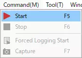
- Click
 on toolbar.
 - Press
F5.
DIO Simulation Screen Description
| Item | Description | Notes | |
|---|---|---|---|
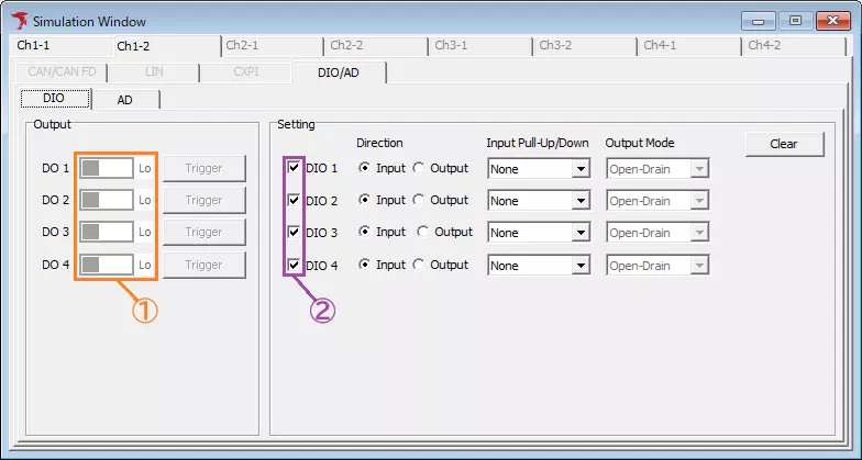
| Output | DIO (Area ①) | Sets DIO output level. Toggle meanings:Lo: output Lo levelHi: output Hi level | Unavailable when Direction is Input. |
 button button | Opens DIO Output Trigger Setting dialog to configure event-trigger usage and conditions for changing DIO output level. | ||
| Setting | DIO (Area ②) | Enable/disable DIO. Checkbox ON = enabled, OFF = disabled. | |
| Direction | Sets DIO direction.Input: input directionOutput: output direction | ||
| Input Pull-Up/Down | Sets pull-up or pull-down resistor enable/disable.None: both disabledPull-Up: pull-up enabledPull-Down: pull-down enabled | Unavailable when Direction is Output. | |
| Output Mode | Sets output mode.Push-Pull: push-pull modeOpen-Drain: open-drain mode | Unavailable when Direction is Input. | |
 button button | Shows confirmation dialog.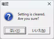 Click Yes to initialize all items. | ||
DIO Output Trigger Setting Dialog
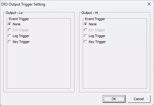
Configures whether to use event trigger and trigger conditions for changing DIO output level.
When an event configured as Output: Lo is detected, output changes to Lo. When Output: Hi event is detected, output changes to Hi.
| Item | Description | Notes |
|---|---|---|
| None | Event trigger is not used. | |
| Ext Trigger | Detects port input as event. | Under development, currently unavailable. |
| Log Trigger | Detects specified monitoring log as event. | |
| Key Trigger | Detects specified key input as event. |
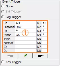
Log Trigger Settings
In Log Trigger, configured logs can be detected as events. Various conditions such as specific data/errors can be set.
Log Trigger Screen
| Screen menu | Description |
|---|---|
| Event condition (Area ①) | Displays log condition used for event detection. Double-click to open Trigger Setting dialog and configure conditions. |
 button button | Opens Trigger Setting dialog to configure event log conditions. |
For details of Trigger Setting dialog, see Trigger Setting dialog.
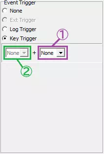
Key Trigger
Key Trigger detects keyboard input as events. This enables operations such as frame transmission by key input.
| Item | Description | Notes |
|---|---|---|
| Main key (Area ①) | Sets trigger key. Options: None, A-Z, 0-9, F1-F12, SPACE | If None is set, key-trigger detection and log-data transmission by key are disabled. |
| Sub key (Area ②) | Sets modifier key used with main key. Options: None, Alt, Ctrl, Shift | Sub-key-only detection is not supported. |