Trigger Function
Using the trigger function, you can automatically start/stop logging during monitoring when predefined conditions are detected.
- When a specific log is detected (Log Trigger)
- When a specific key is pressed (Key Trigger)
This lets you save logs efficiently only at required timing.
Trigger settings are configured in Trigger Window.
Trigger Modes
Available trigger modes and behavior are as follows.
| Trigger Mode | Behavior |
|---|---|
| Free Run | Disables trigger function. Logging starts/stops with monitoring start/stop. |
| Triggered | Enables trigger function. Logging starts/stops when configured trigger conditions are detected. If stop trigger is detected once, monitoring also stops. |
| ReTriggered | Enables trigger function. Logging starts/stops when configured trigger conditions are detected. When stop trigger is detected the 64th time, monitoring also stops. |
In ReTriggered mode, both start trigger and stop trigger must be configured. A new log file is created each time a start trigger is detected.
Basic Operation
Log Trigger Setup
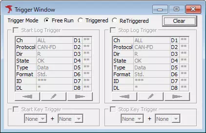
1. Open Trigger Window
Select Trigger Window from the menu or toolbar.
2. Enable trigger function
In "Trigger Mode", select "Triggerd" or "ReTriggerd" from the radio button options. This enables the trigger function and allows you to configure the following items.
- Start Log Trigger
- Stop Log Trigger
- Start Key Trigger
- Stop Key Trigger
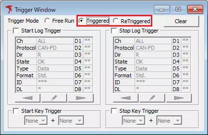
In the example above, "Triggerd" is selected.
3. Enable start or stop log trigger
Turn ON the "Start Log trigger" or "Stop Log Trigger" checkbox. This enables Start Log Trigger or Stop Log Trigger.
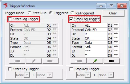
In the example above, the "Stop Log Trigger" checkbox is turned ON to enable Stop Log Trigger.
4. Open Trigger Setting dialog
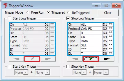
Click  inside the section enabled in step 3, or double-click the trigger-condition display area.
Trigger Setting dialog appears.
5. Set log trigger conditions
In Trigger Setting, configure conditions such as protocol and channel.

In the example above, stop log trigger is set to when DIO4 changes from Hi to Lo.
See Trigger Setting dialog for details.
6. Register log trigger conditions
Click  in
Trigger Setting.
Configured conditions are registered and displayed in the trigger-condition area of Trigger Window.


7. Start monitoring
When monitoring starts, logging starts/stops according to detected trigger conditions.
Key Trigger Setup
1. Open Trigger Window
Select Trigger Window from the menu or toolbar.
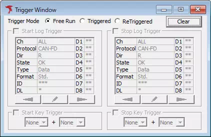
2. Enable trigger function
In "Trigger Mode", select "Triggerd" or "ReTriggerd" from the radio button options. This enables the trigger function and allows you to configure the following items.
- Start Log Trigger
- Stop Log Trigger
- Start Key Trigger
- Stop Key Trigger
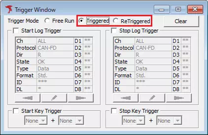
In the example above, "Triggerd" is selected.
3. Enable start or stop key trigger
Turn ON the "Start Key trigger" or "Stop Key Trigger" checkbox. This enables Start Key Trigger or Stop Key Trigger.
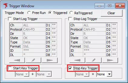
In the example above, the "Stop Key Trigger" checkbox is turned ON to enable Stop Key Trigger.
4. Set key trigger conditions
Set key conditions using the main-key and sub-key pull-down menus.
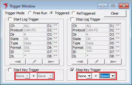
In the example above, Space key is set as stop key trigger.
See Key Trigger for details.
7. Start monitoring
When monitoring starts, logging starts/stops according to configured key input conditions.
Trigger Window
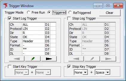
| Item | Description | Notes |
|---|---|---|
| Trigger Mode | Selects trigger mode. Radio button options are: Free Run, Triggered, ReTriggered | See Trigger Modes. |
| Start Log Trigger | Configures start log trigger that starts logging when configured log is detected. | See Log Trigger. |
| Stop Log Trigger | Configures stop log trigger that stops logging when configured log is detected. | See Log Trigger. |
| Start Key Trigger | Configures start key trigger that starts logging when configured key input is detected. | See Key Trigger. |
| Stop Key Trigger | Configures stop key trigger that stops logging when configured key input is detected. | See Key Trigger. |
 button | Displays a confirmation dialog.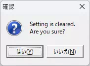 Click Yes to delete all trigger conditions and change mode to Free Run. |
Log Trigger
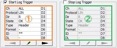
| Item | Description | Notes | |
|---|---|---|---|
| Start Log Trigger | Start Log Trigger | Enables/disables start log trigger. [ON] Enable start log trigger. [OFF] Disable start log trigger. | Disabled when Trigger Mode is Free Run. |
| Trigger condition display area (Area ①) | Displays start log trigger conditions. | Double-click to open Trigger Setting and configure start log trigger conditions, same as clicking . | |
| button | Opens Trigger Setting to configure start log trigger conditions. | ||
 button | Scrolls start trigger condition display to previous page. | ||
 button | Scrolls start trigger condition display to next page. | ||
| Stop Log Trigger | Stop Log Trigger | Enables/disables stop log trigger. [ON] Enable stop log trigger. [OFF] Disable stop log trigger. | Disabled when Trigger Mode is Free Run. |
| Trigger condition display area (Area ②) | Displays stop log trigger conditions. | Double-click to open Trigger Setting and configure stop log trigger conditions, same as clicking . | |
| button | Opens Trigger Setting to configure stop log trigger conditions. | ||
| button | Scrolls stop trigger condition display to previous page. | ||
| button | Scrolls stop trigger condition display to next page. | ||
Trigger Setting Dialog
Configure conditions for Start Trigger or Stop Trigger.
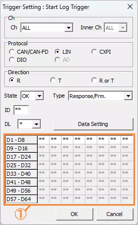
| Item | Description | Notes | |
|---|---|---|---|
| Ch | Ch | Sets the log Ch used for log trigger conditions (number assigned per MicroPeckerX unit). Pull-down options are: ALL, 1, 2, 3, 4 | When "ALL" is selected, all CH are included in the condition. |
| InnerCh | Sets the internal Ch used for log trigger conditions (internal Ch number of one MicroPeckerX unit). Pull-down options are: ALL, 1, 2 | When "ALL" is selected, all internal Ch are included in the condition. | |
| Protocol | Sets the protocol of logs used for log trigger conditions. Radio button options are: CAN/CAN-FD, LIN, CXPI, DIO, AD | CXPI cannot be selected. | |
| Direction | Sets the direction of logs used for log trigger conditions. Radio button options are: R, T, R or T | R means receive only, T means transmit only, and R or T means both transmit and receive. This item cannot be selected when Protocol is set to DIO or AD. | |
| Protocol-specific Settings (Area ①) | Displays settings for the protocol selected in Protocol. | For details about the settings for each protocol, see the following sections. 【CAN/CAN FD】 CAN/CAN FD Protocol-specific Settings 【LIN】 LIN Protocol-specific Settings 【DIO】 DIO Protocol-specific Settings 【AD】 AD Protocol-specific Settings | |
 Button | Click to save configured log trigger conditions and close the dialog. | ||
 Button | Click to discard configured log trigger conditions and close the dialog. | ||
CAN/CAN FD Protocol-specific Settings
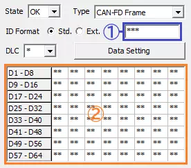
| Item | Description | Notes | |
|---|---|---|---|
| State | Sets the state of logs used for log trigger conditions. Pull-down options are: OK, NG | ||
| Type | Sets the log type used for log trigger conditions. Pull-down options vary depending on selected State: 【OK】 CAN-FD Frame, CAN Data Frame, CAN Remote Frame 【NG】 All Error, Bus Error, Error Warning, Error Passive, Bus Off Entry, Bus Off Recovery, Overload, Bus Lock, Arbitration Lost, Stuff Error, Form Error, Ack Error, CRC Error, Recessive Bit Error, Dominant Bit Error, Ack Delimiter Error | ||
| ID Format | Sets the CAN ID format of logs used for log trigger conditions. Pull-down options are: Std., Ext. | This item is shown only when OK is selected for State. | |
| ID (Area ①) | Sets the CAN ID of logs used for log trigger conditions in hexadecimal. | This item is shown only when OK is selected for State. | |
| DLC | Sets the data length of logs used for log trigger conditions. Pull-down options are: 0, 1, 2, 3, 4, 5, 6, 7, 8, 12, 16, 20, 24, 32, 48, 64, * | This item is shown only when OK is selected for State. | |
 Button | Click to open the "Data Setting" dialog and configure per-byte data of logs used for log trigger conditions. | This item is shown only when OK is selected for State. | |
| Data Display Area (Area ②) | Displays per-byte data of logs used for log trigger conditions configured in the "Data Setting" dialog. | Double-clicking this area opens the "Data Setting" dialog (same as clicking ), where per-byte data can be configured. This item is shown only when OK is selected for State. | |
CAN/CAN FD Data Setting Dialog
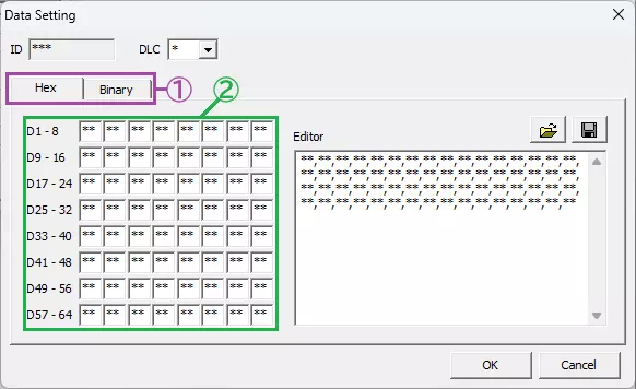
Configures log data used for log trigger conditions.
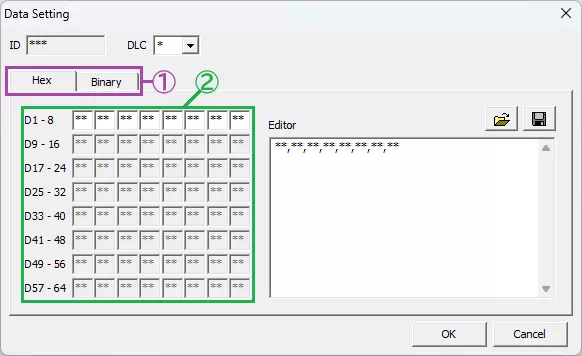
Data display format can be switched between Hex (hexadecimal) and Binary via tabs.
| Item | Description | Notes |
|---|---|---|
| ID | Displays the CAN ID configured in the Trigger Setting dialog in hexadecimal. | ID cannot be changed in this dialog. |
| DLC | Sets the data length of logs used for log trigger conditions. Pull-down options are: 0, 1, 2, 3, 4, 5, 6, 7, 8, 12, 16, 20, 24, 32, 48, 64, * | When data length is changed, the configurable range in the data setting area and editor changes accordingly. The asterisk (*) is equivalent to selecting "8" (or "64" when Type is set to "CAN-FD Frame" in the Trigger Setting dialog). |
| Display Format Tabs (Area ①) | Switches the data display format by tabs. "Hex" displays hexadecimal and "Binary" displays binary. | |
| Data Setting Area (Area ②) | Sets per-byte data of logs used for log trigger conditions. Enter data values in hexadecimal on the "Hex" tab and in binary on the "Binary" tab. | You can also use an asterisk (*) in data values. Bits specified with an asterisk are not used in evaluating trigger conditions. |
| Editor Area | Sets each byte of data in CSV format. Enter data values in hexadecimal on the "Hex" tab and in binary on the "Binary" tab. | You can also use an asterisk (*) in data values. Bits specified with an asterisk are not used in evaluating trigger conditions. |
 Button | Click to open a file dialog and load a CSV file saved with  , then reflect it in the editor display content. | |
| Button | Click to open a file dialog and save the editor display content to any file in CSV format. | |
 Button | Click to save settings and close the dialog. | |
 Button | Click to discard settings and close the dialog. |
The data setting area and editor are linked. Changing values in either one automatically updates the other.
LIN Protocol-specific Settings
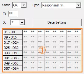
| Item | Description | Notes | |
|---|---|---|---|
| State | Sets the state of logs used for log trigger conditions. Pull-down options are: OK, NG | ||
| Type | Sets the log type used for log trigger conditions. Pull-down options vary depending on selected State: 【OK】 Header, Response/Frm., Wakeup, Sleep, B-Sleep 【NG】 All Error, SyncBrk. Long, SyncBrk. Short, Parity Err., ShortMsg Err., Checksum Err., NoRes. Err., Bit Err., Framing Err., SyncField Err., H. Timeout, UART Err. | ||
| ID | Sets the LIN ID of logs used for log trigger conditions in hexadecimal. | This item is shown only when one of the following is selected for Type: Header, Response/Frm. | |
| DL | Sets the data length of logs used for log trigger conditions. Pull-down options are: 1, 2, 3, 4, 5, 6, 7, 8, * | This item is shown only when Response/Frm. is selected for Type. | |
| Button | Click to open the "Data Setting" dialog and configure per-byte data of logs used for log trigger conditions. | This item is shown only when Response/Frm. is selected for Type. | |
| Data Display Area (Area ①) | Displays per-byte data of logs used for log trigger conditions configured in the "Data Setting" dialog. | Double-clicking this area opens the "Data Setting" dialog (same as clicking ), where per-byte data can be configured. This item is shown only when Response/Frm. is selected for Type. | |
LIN Data Setting Dialog
Configures log data used for log trigger conditions.
Data display format can be switched between Hex (hexadecimal) and Binary via tabs.
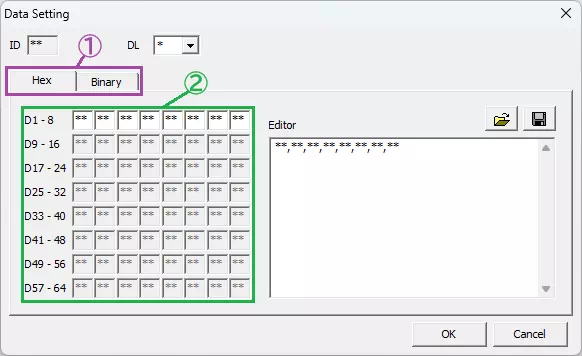
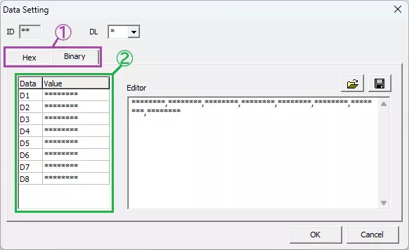
| Item | Description | Notes |
|---|---|---|
| ID | Displays the LIN ID configured in the Trigger Setting dialog in hexadecimal. | ID cannot be changed in this dialog. |
| DL | Sets the data length of logs used for log trigger conditions. Pull-down options are: 1, 2, 3, 4, 5, 6, 7, 8, * | When data length is changed, the configurable range in the data setting area and editor changes accordingly. The asterisk (*) is equivalent to selecting "8". |
| Display Format Tabs (Area ①) | Switches the data display format by tabs. "Hex" displays hexadecimal and "Binary" displays binary. | |
| Data Setting Area (Area ②) | Sets per-byte data of logs used for log trigger conditions. Enter data values in hexadecimal on the "Hex" tab and in binary on the "Binary" tab. | You can also use an asterisk (*) in data values. Bits specified with an asterisk are not used in evaluating trigger conditions. |
| Editor Area | Sets each byte of data in CSV format. Enter data values in hexadecimal on the "Hex" tab and in binary on the "Binary" tab. | You can also use an asterisk (*) in data values. Bits specified with an asterisk are not used in evaluating trigger conditions. |
| Button | Click to open a file dialog and load a CSV file saved with , then reflect it in the editor display content. | |
| Button | Click to open a file dialog and save the editor display content to any file in CSV format. | |
| Button | Click to save settings and close the dialog. | |
| Button | Click to discard settings and close the dialog. |
The data setting area and editor are linked. Changing values in either one automatically updates the other.
DIO Protocol-specific Settings
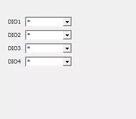
| Item | Description | Notes | |
|---|---|---|---|
| DIO1 | Sets DIO data levels used for log trigger conditions. Pull-down options are: *, 0(Lo), 1(Hi), 0(Lo)->1(Hi), 1(Hi)->0(Lo) | "0(Lo)->1(Hi)" means the instant when the level changes from 0(Lo) to 1(Hi), and "1(Hi)->0(Lo)" means the instant when the level changes from 1(Hi) to 0(Lo). Selecting "*" excludes that DIO data level from the log trigger conditions. | |
| DIO2 | |||
| DIO3 | |||
| DIO4 | |||
AD Protocol-specific Settings
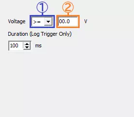
| Item | Description | Notes | |
|---|---|---|---|
| Voltage | Area ① | Sets the threshold comparison condition for AD data used for log trigger conditions. Pull-down options are: >=, <= | Selecting ">=" requires the value to be at or above the threshold; selecting "<=" requires it to be at or below the threshold. |
| Area ② | Sets the AD data threshold used for log trigger conditions. The threshold resolution is 0.1V. | Enter the integer part of the threshold using two digits (add a leading zero for values of 9 or less). | |
| Duration | Sets the duration for which AD data must meet the threshold for a log trigger, in milliseconds. The setting range is 10 to 1000. | ||
An AD data log trigger is activated when the AD data value meets the threshold set in Voltage and remains in that state for at least the time set in Duration, measured from the moment the threshold condition is first met.
Key Trigger

| Item | Description | Notes | |
|---|---|---|---|
| Start Key Trigger | Start Key Trigger | Enables/disables start key trigger. [ON] Enable start key trigger. [OFF] Disable start key trigger. | Disabled when Trigger Mode is Free Run. |
| Main Key (Area ①) | Sets main key condition for start key trigger. Options: None, A, B, ..., Z, 0, 1, ..., 9, F1, F2, ..., F12, SPACE | If main key is None, start key trigger is disabled. | |
| Sub Key (Area ②) | Sets sub key combined with main key for start key trigger. Options: None, Alt, Ctrl, Shift Set None when no sub key is used. | You cannot set start key trigger with only sub key. | |
| Stop Key Trigger | Stop Key Trigger | Enables/disables stop key trigger. [ON] Enable stop key trigger. [OFF] Disable stop key trigger. | Disabled when Trigger Mode is Free Run. |
| Main Key (Area ③) | Sets main key condition for stop key trigger. Options: None, A, B, ..., Z, 0, 1, ..., 9, F1, F2, ..., F12, SPACE | If main key is None, stop key trigger is disabled. | |
| Sub Key (Area ④) | Sets sub key combined with main key for stop key trigger. Options: None, Alt, Ctrl, Shift Set None when no sub key is used. | You cannot set stop key trigger with only sub key. | |
Forced Logging Start
When start trigger is enabled, you can force logging to start before start trigger detection by either operation below.
- Select
Command-Forced Logging Startfrom the menu bar.
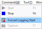
- Click
 on the toolbar.