Device Connection Method
Connection and Disconnection Procedure
This section explains device connection and disconnection procedures.
How to Connect Devices
Connect to Windows PC
Use the included USB cable to connect the MicroPeckerX unit to a USB port on the PC.
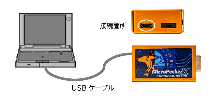
Only the left USB port can be used. Do not remove the cap on the right side.
Connect to DIO/AD
Use a monitor cable to connect the MicroPeckerX unit and DIO/AD. For DIO, connect DIO and GND. For AD, connect A/D and GND.
Monitor cable wiring must be prepared by the user based on Dsub Connector Pin Assignment.
Connect Sync Cable
If you synchronize multiple MicroPeckerX units, connect them using the included sync cable.
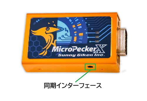
There are two sync interfaces. They are functionally identical. Connect the sync cable according to your installation environment.
Example: 3-unit connection
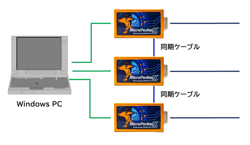
Connect/disconnect sync cables only while monitoring is stopped.
How to Disconnect Devices
Disconnection procedure is as follows.
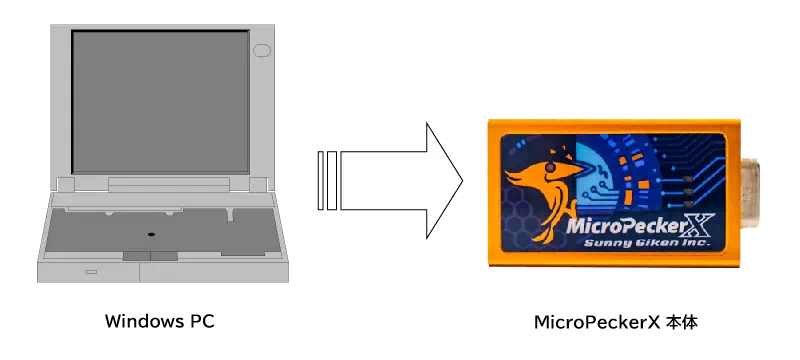
Disconnect MicroPeckerX from Windows PC
Unplug MicroPeckerX from the Windows PC.
Dsub Connector Pin Assignment
Dsub connector pin assignment on the MicroPeckerX unit is as follows.
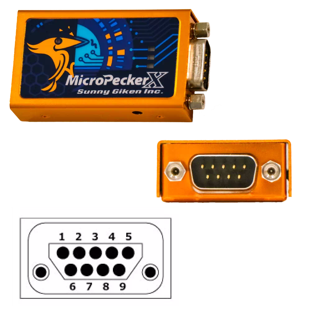
| Pin | Function |
|---|---|
| 1 | DIO4 |
| 2 | DIO2 |
| 3 | ISO-GND |
| 4 | AD |
| 5 | GND (for DIO/AD) |
| 6 | DIO3 |
| 7 | LIN |
| 8 | DIO1 |
| 9 | VBAT |
In DIO/AD mode, gray hatched pins are not used.
DIO/AD GND is pin 5 (GND), not pin 3 (ISO-GND).
Incorrect wiring may damage both the MicroPeckerX unit and the DIO/AD side.