Signal Monitoring and Alerts
Overview
Alerts let you check when signal conditions become active and recover. You can configure multiple conditions per signal. Distinguish the Monitor setting for the value list, the setting that enables alerts, and triggers that start/stop log saving.
| Purpose | Settings / screen to use |
|---|---|
| Check the latest value | Values / Monitor in Display Settings |
| Check activation/recovery of value conditions | Alert in Signal Setting, Alert History |
| Use a condition to start/stop log recording | Start/Stop Signal Trigger in Trigger Window |
| Find occurrences in a saved log | Signal Analysis in Analyze Window |
Configuring Alert Conditions
- Stop monitoring and open Edit for the target signal in Signal Catalog.
- Select the Alert tab. For a derived signal, also use Alert in its editing screen.
- Add a condition with + Add and set its name.
- To also use a condition that supports real-time monitoring while monitoring, select “Monitor + Analysis” as its use. “Analysis only” applies to analysis of recorded logs. State transition is analysis-only.
- Turn on “Enable this condition.”
- Select the required condition from the options available for the signal type.
- Configure the supported thresholds, recovery conditions, notification delay, and notification sound if needed. State transition has no duration or recovery conditions.
- Check the condition summary and enabled state, then confirm with OK.
- For Monitor + Analysis conditions, start monitoring with the intended Set and check Values and Alert History. For analysis-only conditions, analyze a log in Signal Analysis and check the results.
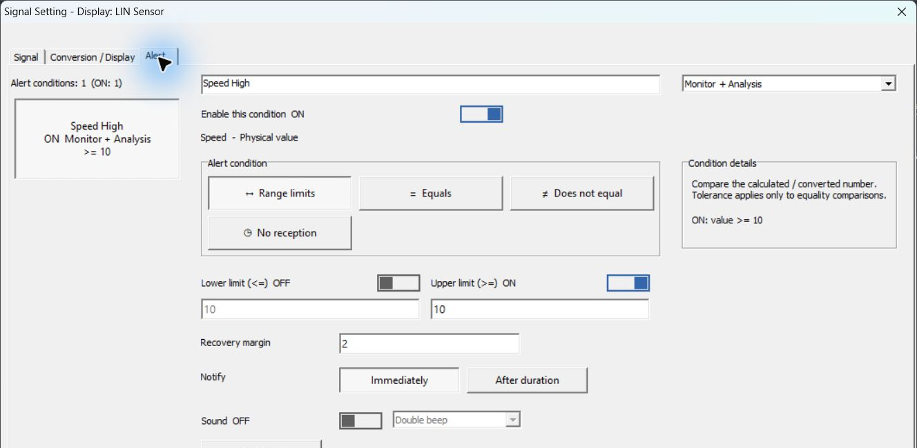
Figure 1. Configuring the Speed High upper-limit condition.
Figure 1 monitors Speed's physical value in LIN Sensor. The condition name is Speed High, usage is Monitor + Analysis, and Enable this condition is ON. Also check ON in the list, the condition summary >= 10, and the enabled count of 1. Set thresholds in the target signal's unit.
Alert Tab Reference
| Item | Description |
|---|---|
| Condition list / Alert conditions | Check registered conditions and the enabled count. Select a condition to edit. |
| Condition name | Set a name to distinguish multiple conditions. |
| Monitor + Analysis / Analysis only | Specify whether the condition is used in real-time monitoring as well, or only in analysis. |
| Enable this condition | Enable or disable the selected condition. |
| Range limits | Use lower/upper-limit conditions. Enable the required side. The upper-limit condition becomes true at or above the configured value. |
| Equals / Does not equal | Test whether values match or differ. |
| Is one of / Is none of | Test whether a value matches any specified state or none of them. |
| Text matches / Text does not match | Test whether strings match or differ. |
| Invalid BCD | Detect values invalid as BCD. |
| State transition | An analysis-only event detecting the instant of a state transition. Not used for monitoring notifications; no duration or recovery conditions are configured. |
| No reception | Test whether the target signal has not been received for the specified time. |
| Condition details | Check the target value, comparison method, and condition summary. |
| Recovery margin | A margin to prevent repeated activation/recovery near a threshold. |
| Notify | Specify Immediately or After duration. |
| Sound / Preview | Configure a notification sound and check it with Preview. |
| + Add / Delete / Undo | Add/delete conditions or undo edits. |
Available conditions and fields depend on the signal type. Do not confuse numeric physical values, Logical states, and strings; check the comparison target in Condition details. For derived signals, the item that checks for missing input updates is shown as No result update.
Upper-Limit Example
Figure 1 selects Range limits, with Lower limit OFF, Upper limit ON at 10, and Recovery margin 2. Notify is Immediately and Sound is OFF. The condition becomes active at Speed 10 km/h or above; once active, it recovers below 10 − 2 = 8 km/h. It remains active at 9 km/h and recovers at 7 km/h.
This test actually transmits SensorFrame with ID 0x10 as Tx from Master Sim., changing the data in the following sequence at 1-second intervals. Speed uses the sample definition conversion Raw × 0.5 − 5.
| Order | D1 D2 (HEX) | Speed | Condition state |
|---|---|---|---|
| 1 | 18 01 | 7 km/h | Upper-limit condition not active. |
| 2 | 22 01 | 12 km/h | Becomes active at 10 km/h or above. |
| 3 | 1C 01 | 9 km/h | Remains active because it has not fallen below the 8 km/h recovery boundary. |
| 4 | 18 01 | 7 km/h | Recovers below 8 km/h. |
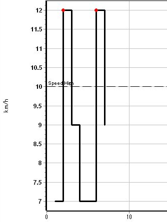
Figure 2. Speed waveform from actual transmitted data and the Speed High upper limit.
In Figure 2, the black line is Speed, the horizontal dashed line at 10 km/h is the Speed High upper limit, and the red point marks the occurrence. The condition remains active when the waveform falls to 9 km/h and recovers when it falls to 7 km/h. Compare occurrence/recovery values and times against the history in Figure 4.
For After duration, set how long the condition must remain true before notification. Choose according to whether you need to detect momentary changes or only abnormalities lasting a specified time.
Alert History Reference
Click Alert History at the upper right of Signal Window.
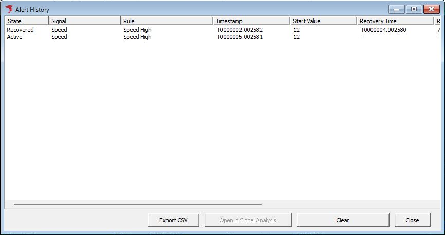
Figure 3. The same actual Speed High history as Figure 4 in a normally sized Alert History window.
The top row in Figure 3 is a Recovered event that occurred at +0000002.002582 with 12 km/h and recovered at +0000004.002580 with 7 km/h. The bottom row is an Active event that occurred at +0000006.002581 with 12 km/h and has not yet recovered.
Export CSV, Open in Signal Analysis, Clear, and Close are at the bottom. Open in Signal Analysis is disabled in this capture. Scroll horizontally to see columns on the right; compare all column values against Figure 4 and its table.
| Item | Description |
|---|---|
| State | Active means the condition is active; Recovered means it has recovered. |
| Signal / Rule | Check the target signal and condition. |
| Timestamp / Start Value | Check activation time and the value at that time. |
| Recovery Time and related fields | Shows recovery time, value, and other details. Scroll horizontally to see later columns. |
| Signal Type / Rule Type / Condition | Compare signal type, monitoring/analysis type used, and condition. Figure 4 shows Native, Monitoring, and >= 10. |
| Export CSV | Export history to CSV. This has a different purpose from signal analysis CSV files and communication logs. |
| Open in Signal Analysis | Investigates the selected event in Signal Analysis. You can also double-click a history row to open it. Monitoring and analysis must be stopped, and data at the occurrence time must remain in the target channel's monitoring buffer. For derived signals, this also includes channels required by their inputs. |
| Clear | Clears recovered history entries. Active rows remain. Save any history you need to keep first. |
| Close | Close the history screen. |
Actual Occurrence and Recovery History
Figure 4 shows the history from monitoring the communication in Figure 2 with Speed High configured as in Figure 1. Check that Signal is Speed, Rule is Speed High, and Condition is >= 10.

Figure 4. Alert History confirming Speed High occurrences and recovery.
On narrow screens, scroll the following table horizontally to check recovery times and values.
| Row | State | Timestamp | Start Value | Recovery Time | Recovery Value |
|---|---|---|---|---|---|
| Top | Recovered | +0000002.002582 | 12 | +0000004.002580 | 7 |
| Bottom | Active | +0000006.002581 | 12 | - | - |
The top row occurred at 12 km/h, remained active through the 9 km/h interval, and recovered at 7 km/h. The bottom row occurred at the next 12 km/h interval and has not yet recovered, so Recovery Time and Recovery Value are “-”. Compare State and timestamps as well as values.
Alerts Versus Signal Trigger
Enabling an alert alone does not make it a condition for starting or stopping log recording. To control log saving using a signal condition, configure the target signal, threshold, comparison direction, and other settings in Start Signal Trigger/Stop Signal Trigger in Trigger Window. Also check the trigger mode and Save Log File.
Select an eligible numeric bus signal for Signal Trigger. Derived signals can be used for alerts but are not eligible for Signal Trigger. See Signal Trigger selection requirements.
Saving and Reusing Conditions
After editing conditions, use Save in the Catalog to save them to MPXSIG. To retain history, use Export CSV in Alert History. Saving conditions and saving recorded history are separate operations.
For saved-log analysis, result output, and use in transmission settings, see the respective instructions.