Graph Display Settings
Overview
Graphs are divided into two tabs, each containing up to four Areas. Configure destinations per signal and compare multiple signals using shared axes in the same Area. Newly configured Sets support up to 32 graph signals across the entire Set. Assignments in Areas not currently visible also count; assigning the same signal to multiple Areas still counts as one signal.
Assigning Signals to Graphs
- Stop monitoring and open Edit for the target signal in Signal Catalog.
- Turn on Graph under Conversion / Display and click the “Graph” button.
- At the top of the Graph dialog, select Graph 1/Graph 2 and the target Area.
- Signals and axes lists the signal being edited in Signal Setting. Select its checkbox.
- Check the signal/axis counts for the selected Area and assignments in the list.
- Adjust shared-axis settings under Selected axis if needed.
- Confirm the Graph dialog with OK, then confirm the parent Signal Setting with OK too.
To display the same signal in another Area, switch destinations at the top and select its checkbox there as well. Checkbox operations apply to the currently selected Graph and Area.
To assign multiple signals in a Set together, open graph settings from Display Settings in Signal Window.
Auto Arranging Unassigned Signals
Use automatic layout to add signals to a graph. It keeps existing assignments and can propose a layout for an empty graph.
- Stop monitoring. If the target Set is not current, open Signal Catalog, select the Set, click
Set Current, and close the Catalog. In Signal Window, verify the Set shown in theSignal Setfield and select the graph tab (Graph 1orGraph 2). - Open
Graph Settings.... Check the target graph tab and clickAuto arrange.... - Under
Signals to add, select the signals you want to display. Check the target Set and Graph at the top and review the Areas, axes, and series inProposed layout. A selected signal with monitoring turned off is markedEnable Monitor. - Click
Use layoutto bring the proposal into Graph Settings. Check the assignments there, then clickOKto apply them. Applying the layout turns on monitoring for signals markedEnable Monitor.
This example adds two speed signals on CH1-1 in the CAN FD Fan Demo Set to an empty Graph 1. Select Target_RPM_demo and Simulated_RPM_demo. The proposal places both signals on the same left axis (L1, rpm) in Area 1.
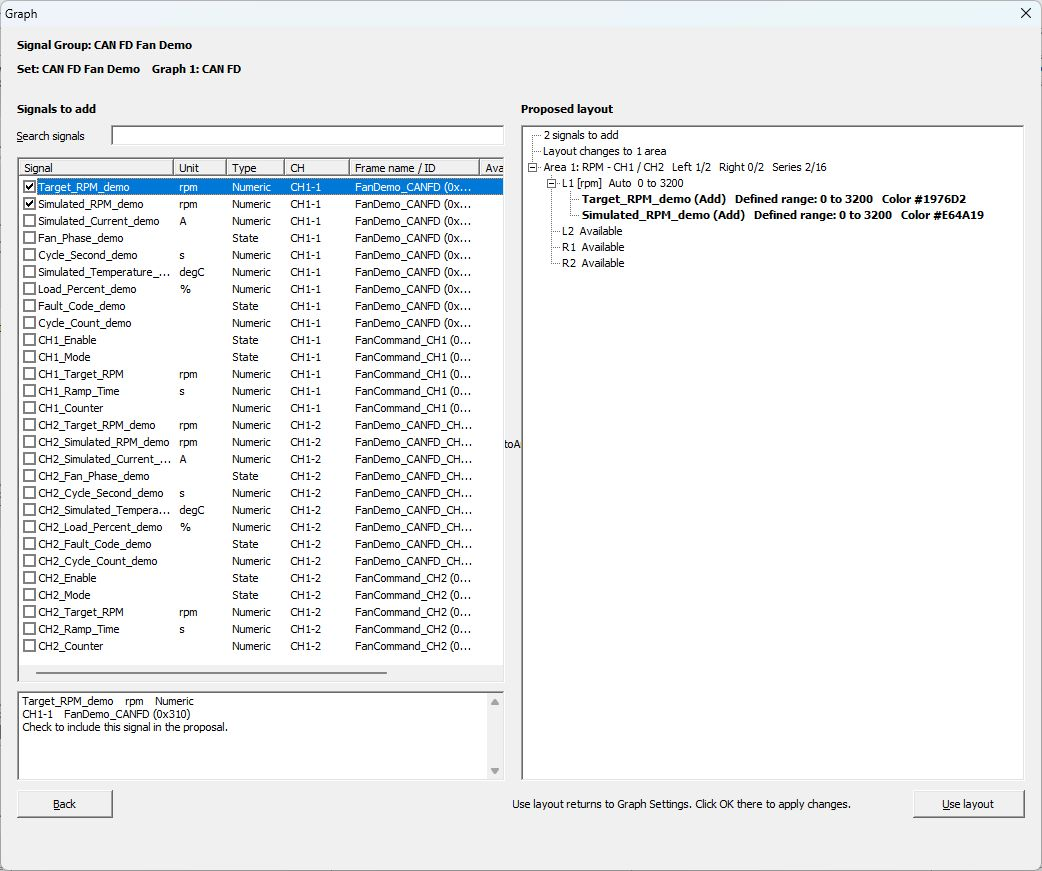
Proposed layout for the two speed signals.
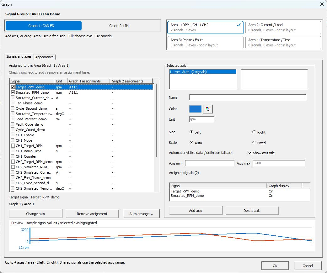
Graph Settings after selecting Use layout, before clicking OK. The Preview at the bottom uses sample values.
Signals without a channel assignment, signals with an unassigned channel dependency, and signals already assigned to a graph (including hidden assignments) cannot be selected. Check Availability for the reason. If there is not enough room on the available axes or for the series, reduce the selection or review the existing layout and assignments in Graph Settings.
You can also open the same tool with signals preselected: select the rows in the Signal Window signal list, right-click, and choose Auto arrange selected signals.... Review the proposed layout and apply it in the same way.
See Changes in Ver.4.10 for other changes in this version.
Signals and axes Reference
| Item | Description |
|---|---|
| Signal Group | Shows the Set being edited. |
| Graph 1 / Graph 2 | Selects the graph tab to configure. |
| Area 1–4 | Selects the Area to configure. You can check its signal and axis counts. |
| not in layout | An Area not visible in the current layout. Check assignments together with the screen layout. |
| Signal checkbox | Configures assignment to the selected Graph/Area. |
| Graph 1/2 assignments | Shows destinations within each tab. A means Area, L/R means left/right axis, and * indicates an assigned signal with Graph turned off. |
| Selected axis | Check axes in the selected Area and signals sharing an axis. |
| Change axis / Remove assignment | Changes the selected signal's axis or removes its assignment. If it has an assignment in the current Area, that assignment is targeted. If it has only one assignment in another Area of the same tab, that assignment is targeted. If there are multiple assignments, switch to the target Area. |
| Add axis / Delete axis | Adds an unassigned numeric axis to the selected Area or deletes the selected axis. Deleting an axis also removes assignments of signals using it. |
| Name / Color / Unit | Configures the axis display name, color, and unit name. |
| Side | Places the axis on the Left or Right. |
| Scale | Selects Auto or Fixed. |
| Axis min / Axis max | Configures the display range for Fixed. |
| Preview | Shows a preview of the selected axis or signal. |
Using Shared Axes
This FanDemo example uses Graph 2/Area 1. Target_RPM_demo and Simulated_RPM_demo share the L1 axis. Under Selected axis, its range is Fixed at 0–3200 rpm.
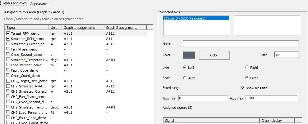
Figure 1. Assignments in Graph 2/Area 1. Both signals show A1 L1 and unit rpm.
In Signal Window, open the “CH1 vs CH2” tab for Graph 2 and check the Area 1 legend. The light blue line in Figure 2 is target rotational speed (Target_RPM_demo), and the dark blue line is actual rotational speed (Simulated_RPM_demo). Both are signals on CH1-1, ID 0x310; [Left 1] in the legend corresponds to L1 in Figure 1. Read both values using the rpm scale on the left. For example, just after the start, the target stays at 1,000 rpm while actual speed rises from about 400 rpm.
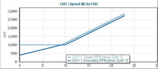
Figure 2. Received waveforms for target/actual rotational speed on channel 1 using the same left axis.
Signals on the same axis use the same scale. Changing an axis range affects all signals sharing it. Check the signal list under Selected axis before changing settings.
To assign a numeric signal to an existing shared axis, its unit must match the axis unit exactly, including letter case. Use separate axes for signals with different units. State displays use dedicated axes. Changing a unit name does not convert physical values.
For new configurations, one Area supports up to four axes (two left, two right) and 16 signal assignments, including hidden assignments. Older settings may retain configurations exceeding the axis limit or Set-wide assigned-signal limit. Operations that increase the excess are not allowed; reduce assignments or axes to return within limits. If you cannot change assignments or axes, check the on-screen message and existing axis configuration.
Auto and Fixed
In “Graph Settings,” select the target Graph and Area, then configure “Scale” for L1 under Selected axis. Auto adjusts the vertical axis to the displayed data. Fixed uses the range specified by “Axis min” and “Axis max.”
Figures 3 and 4 display data from the same reception session. For comparison, target and actual rotational speeds on CH1-1, ID 0x310, are assigned to Area 1 in both Graph 2 and Graph 1. Both horizontal axes cover 0–30 seconds from the start; waveforms extend to about 17.3 seconds, when monitoring stopped.
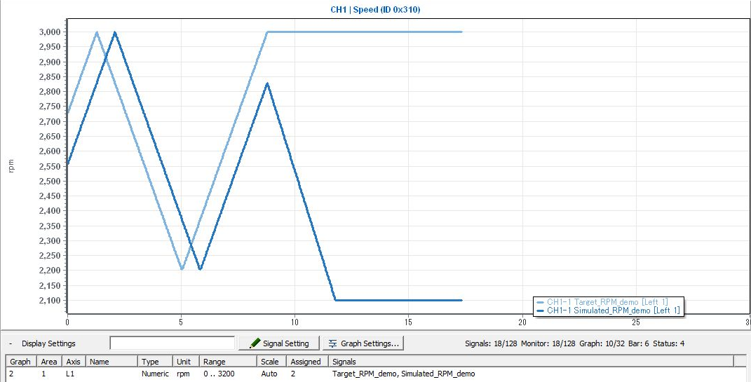
Figure 3. Auto (Graph 2/Area 1). Vertical ticks are 50 rpm apart, enlarging speed changes and separation between the lines.
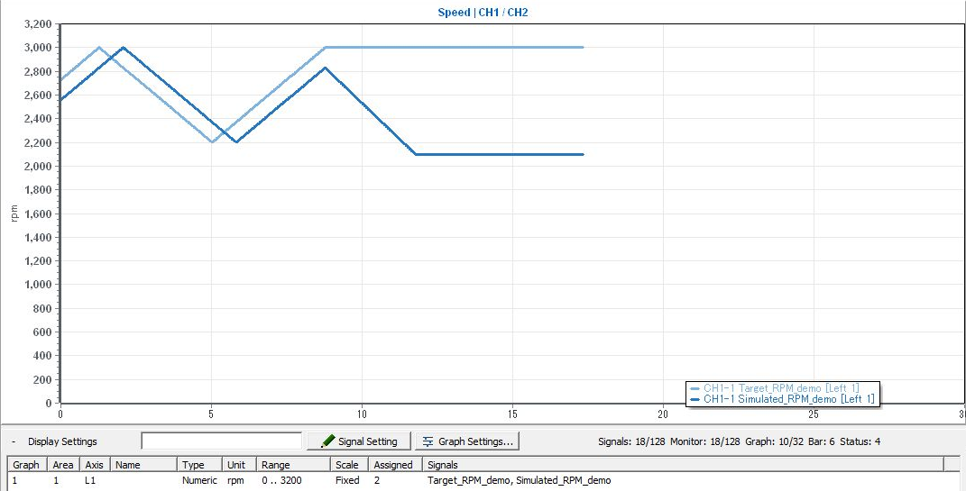
Figure 4. Fixed (Graph 1/Area 1). Displays 0–3,200 rpm in 200 rpm increments. At about 15 seconds in both images, the target is 3,000 rpm and actual speed is 2,100 rpm, a difference of 900 rpm. Use matching Fixed upper/lower bounds when comparing speed across measurements.
Appearance Reference
In this example, editing is limited to Selected graph and area. The curves below are a preview for checking appearance.
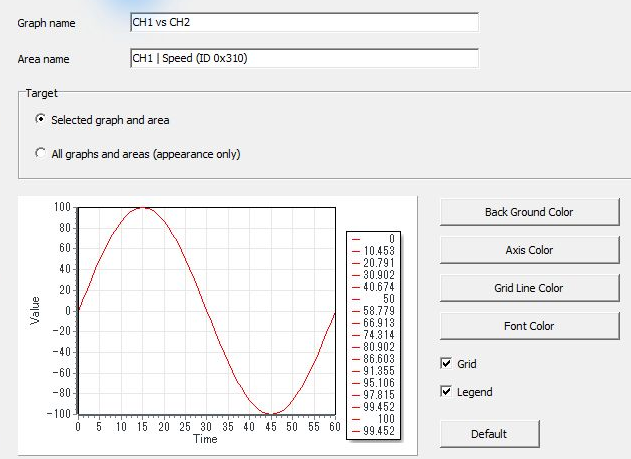
Figure 5. Appearance scope and appearance preview.
| Item | Description |
|---|---|
| Graph name / Area name | Sets graph tab and Area names. |
| Selected graph and area | Edits appearance for the selected graph and Area. |
| All graphs and areas (appearance only) | Selects all graphs/Areas as the scope for appearance changes. |
| Back Ground Color | Sets the background color. |
| Axis Color / Grid Line Color / Font Color | Sets axis, grid, and text colors. |
| Grid / Legend | Configures grid/legend visibility. |
| Default | Restores default appearance settings. Check the scope before running it. |
The sample curves in Appearance are not measured data either.
Display Operations in Signal Window
Use Graph 1/Graph 2 and the layout selector to switch display destinations. Zooming the time range or resetting it from the “…” menu links the time axes of Areas in the same graph tab. Use Pause/Resume to pause/resume graph display.
To retain an image of one Area, select it and use Save Graph Area/Copy Graph Area in the “…” menu. To capture the entire visible tab, use Save Graph Tab/Copy Graph Tab in the graph's right-click menu.
When sharing an image, also record the Set name, target signals, channels, units, and time range. An image alone cannot be used to recheck source frames, so save logs and MPXSIG as needed.
Pausing graphs and saving images are separate from stopping all monitoring. See Signal Window for details.
To compare saved-log waveforms with source frames, see Signal Analysis. To retain values/images, see Recording and Exporting Results.