Configuring Transmission Frames from Catalog
Relationship Between Definitions and Transmission Data
Communication definitions in Signal Catalog can also be used to check transmission frame conditions and edit initial data. Importing into Catalog or configuring the display in Signal Window alone does not start transmission. Configure transmission timing and execution conditions in Send Frame mode.
Creating Transmission Frames from Catalog
Preparation and Entry Point
- Stop monitoring and prepare CAN/CAN FD frame definitions by importing a DBC file or defining them manually. Membership in a monitoring Set is not required for transmission.
- Select the connected target CH and Send Frame mode in Simulation Window.
- Right-click the add (+), edit, or copy button in Send Frame, then open Frames from Catalog from the menu.
- Check CH and Source, then verify Frame, ID (HEX), Format, Bytes, Cycle (ms), and Availability in the Catalog Frames candidate list.
Adding Candidates
- Check the candidates to add. Selecting a row specifies the target for Details; it is separate from checking the candidate.
- Select a row and open Details to adjust the initial data and cycle as needed. If the source definition has a cycle of 0 ms, enter a value from 0.1 to 60000 ms in increments of 0.1 ms here. The initial value for candidates with no specified cycle is 1000 ms.
- Click OK to close Details, then check the resulting slot numbers, frames, cycles, and HEX data in Frames after Apply in the lower section.
- If you are only adding frames, finalize the changes with Add N Frames, where N is the number of frames. The total, including existing slots, is limited to 28 slots.
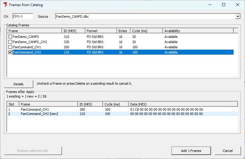
This example shows the state before applying changes, with FanCommand_CH2 (ID 210) checked to add one new frame alongside one existing frame. Check new and Add 1 Frames in the lower section.
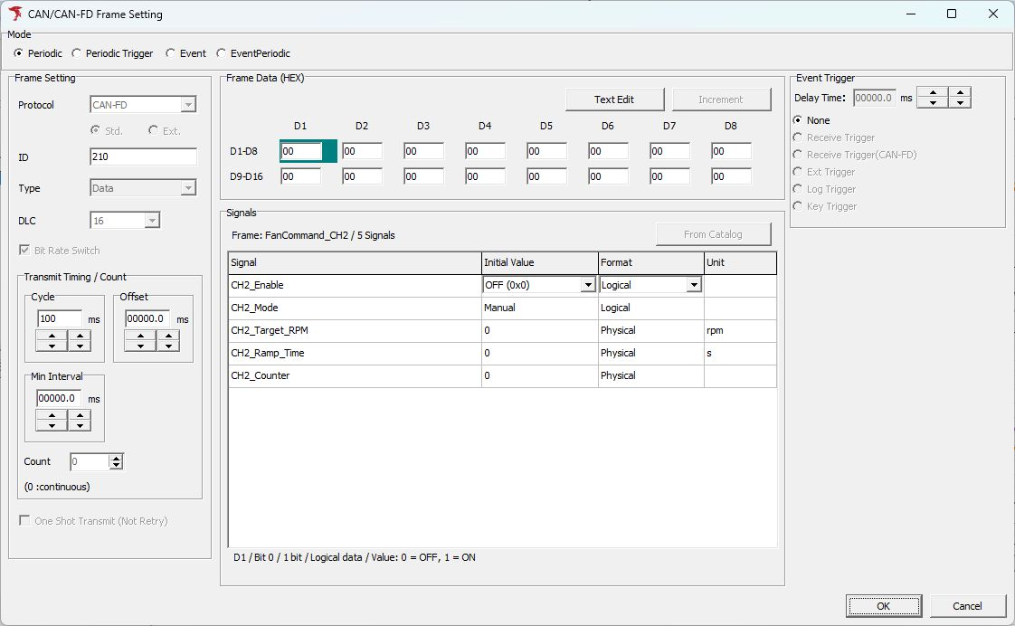
In Details, check and edit the selected candidate's cycle and initial signal values. The figure shows HEX data corresponding to a Logical value of OFF for CH2_Enable and a Physical value of 0 rpm for CH2_Target_RPM.
Replacing an Existing Slot
- Select a candidate row in the upper section. If the source definition has a cycle of 0 ms, enter a value from 0.1 to 60000 ms in increments of 0.1 ms in Details, then confirm with OK.
- Select the target candidate row in the upper section again after clicking OK in Details. Also select an existing slot row in Frames after Apply in the lower section, then click Replace selected slot.
- In the Replace slot confirmation, verify that the Catalog data and initial periodic transmission settings will be applied and that the selected slot's settings will be reset, then select Replace.
- Check the resulting list in the lower section and confirm with the final Apply button. If you are also adding frames, verify those additions as well.
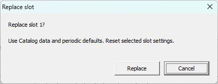
Clicking OK in Details or confirming a replacement only changes the draft within this dialog. The original Simulation settings are not updated until the final Add/Apply operation. Uncheck a candidate or press Delete on a pending row to remove that planned change. Cancel discards unapplied draft changes.
If Catalog, CH assignments, Device settings, or Simulation settings change while the dialog is open, check the reason, close the dialog with Cancel, and reopen it. After applying the changes, proceed to the initial values in the next section and the pre-transmission checks.
Editing Initial Values in the Frame Settings Dialog
- Open CAN/CAN-FD Frame Setting for the transmission slot. If a definition has already been applied, the saved definition appears under Signals.
- To apply a new definition or select a different one, click From Catalog. In Select CAN/CAN FD Frame from Catalog, check Source, Frame, ID, format, and length, then click Use Frame. Click OK in the confirmation dialog to apply it to the frame settings dialog.
- Select the target signal under Signals, choose an available format from Physical, Logical, or Raw, and enter the value. When selecting a different frame definition, also check the initial byte sequence carried over.
- Check the resulting HEX data, frame format, ID, and DLC.
- Click OK in CAN/CAN-FD Frame Setting to confirm the slot configuration.
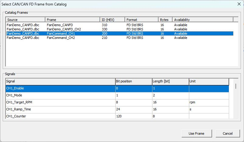
The example shows FanCommand_CH1 (ID 200, 16 bytes) selected from FanDemo_CANFD.dbc. The lower section shows the bit positions, lengths, and units of the signals. Click Use Frame to proceed with applying the definition.
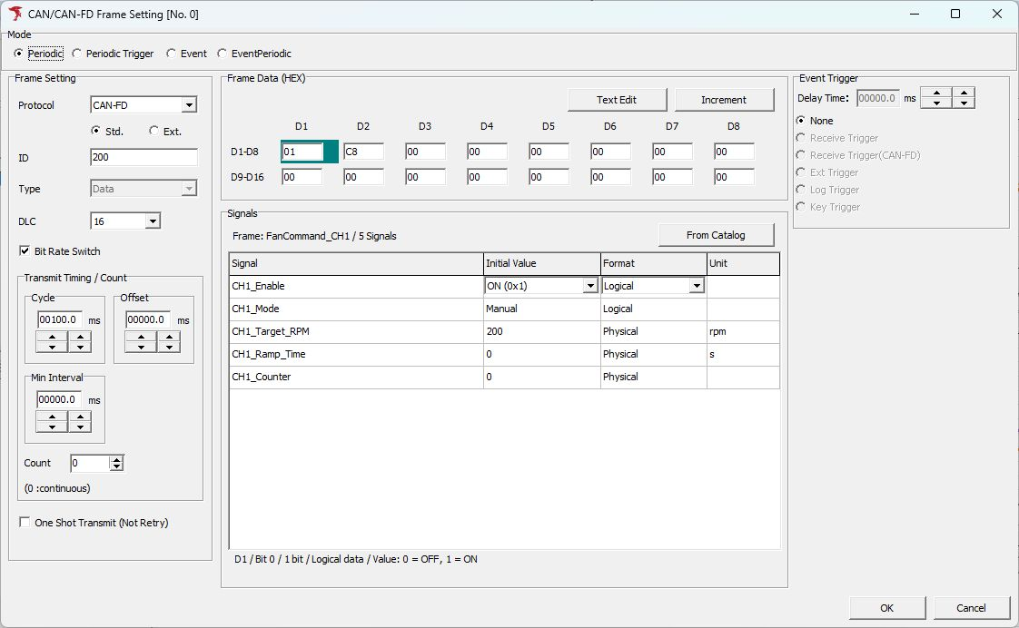
In this figure, CH1_Enable is ON and CH1_Target_RPM is 200 rpm, giving 01 C8 00 as the first 3 bytes. This uses a different definition from the Speed/State sample below.
Details within Frames from Catalog is used to edit the initial values and cycle of the candidate selected in that dialog. To use a different definition, select it in the candidate list, then confirm with the final Add or Apply button.
For example, in the sample definitions in this chapter, setting Speed to a physical value of 10 km/h gives a Raw value of 30 (0x1E), and setting State to On gives 0x01. Verify that the first 2 bytes are 1E 01. Also check bits not used by signals and any subsequent bytes.
For Physical, enter a value within the range that the definition's inverse conversion can convert to Raw. For Logical, select a defined state. For Raw, enter a value within the range supported by the signal's bit width and signedness. A derived signal's calculated result cannot be assigned directly to bits in the transmission data. See also Signal Definitions and Conversion.
Checking and Saving After Applying Changes
The definition applied when generating or editing a frame is retained as the definition associated with its transmission settings. Do not assume that subsequent Catalog edits automatically update existing transmission data. Apply the required definition again with From Catalog and check the initial values.
Also check whether transmission slots are enabled, cycles, counts, event conditions, data, and any data changes during transmission such as Increment or Pattern. Save settings using normal configuration saving, and save the entire Catalog using MPXSIG.
Review the safety precautions, then follow the Send Frame procedure to start actual transmission. After transmission, compare the frames in Monitor Window with the values in Signal Window. To inspect captured logs later, use Signal Analysis.