Defining Bus Signals Manually
Overview
Signal Setting configures the conditions for extracting values from frames, conversion methods, display destinations, and alerts. Add a signal with “+ Signal” in the Catalog, or open a registered signal with “Edit.”
Basic Manual Registration Procedure
- Select the target Set in Signal Catalog and click “+ Signal.”
- Configure Name, Protocol, CH, Direction, ID, DL, and other settings.
- Configure Endian, Bit Position, Data Length, and Signed, and check the range in the bit diagram.
- Configure conversion and display destinations under Conversion / Display.
- If needed, configure monitoring conditions on the Alert tab.
- Click OK, then check In Set, channel, and display settings in the Catalog.
Distinguish the signal definition from per-Set channel and display settings. Check the Set shown in the screen title. Editable items may differ for signals that exist only in the Catalog or have an unavailable channel.
Signal Tab Reference
Target_RPM_demo in FanDemo targets a CAN FD frame with standard ID 0x310. DL is the full frame length of 16 bytes, while Data Length is the 16-bit signal selected in red. If the first two bytes are 98 0B, the Raw value extracted in Little Endian is 0x0B98 (2968). With the conversion settings below, this corresponds to 2968 rpm.
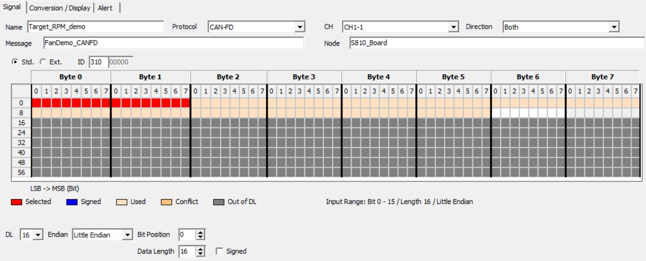
Figure 1. Bit positions of Target_RPM_demo.
| Item | Description |
|---|---|
| Name | Signal name. Identify signals using the channel and ID as well as the name. |
| Protocol | Select CAN or CAN FD. |
| CH | Actual channel associated with the signal. Check the channel used in the Set. |
| Direction | Target transmission/reception direction. Both includes both directions. |
| Message / Node | Check frame names, node names, and other information obtained from communication definitions. |
| ID | Specify the frame ID in hexadecimal. Match Std./Ext. to actual frames as well. Standard and extended IDs are separate conditions even when their numeric values match. |
| DL | Frame data length in bytes, distinct from the signal's bit length. |
| Endian | Select Little Endian or Big Endian extraction. |
| Bit Position | Specify the signal's start bit position. |
| Data Length | Specify the signal's number of bits. |
| Signed | Turn on to treat the value as a signed number. |
| Bit diagram | Check positions and overlaps using the Selected, Signed, Used, Conflict, and Out of DL colors. |
If the DBC includes multiplexed signals, also check the selector and expected branch values. Do not treat a signal as having a valid current value when the current selector value does not match its branch condition.
Example: Extracting the First Byte as a Number
To use the first byte of a CAN/CAN FD frame with ID 0x100 (standard ID) and DL 8, select Little Endian, Bit Position 0, Data Length 8, and Signed OFF. For data “1E 01 …,” the Raw value is hexadecimal 1E = decimal 30.
For Big Endian signals or signals crossing byte boundaries, compare the bit numbering in the signal specification with the bit diagram. Changing only Endian does not necessarily make the same start bit refer to the same range.
Conversion / Display Tab
Value Conversion
This is a conversion example for the same signal. Because the Value Table Range specifies “Raw × 1 + 0” with unit rpm, entering 100 in Raw sample in Conversion Preview displays 100 rpm.
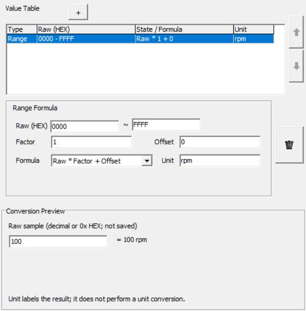
Figure 2. Conversion settings and preview for Target_RPM_demo.
| Option | Description |
|---|---|
| Raw | Uses the extracted value without conversion. |
| Formula | Converts to a numeric value using a formula with a factor, offset, or other operations. |
| Value Table | Defines conversions for Raw ranges or state names corresponding to Raw values. |
| BCD | Converts data represented as BCD. |
| ASCII | Treats data as a string. Set the signal length in bytes. |
Use + in Value Table to add a row, then configure its Raw range, Factor, Offset, Formula, Unit, state name, and other properties. Use the up/down buttons to adjust the order; select and delete unwanted rows.
Different formula types can produce different results with the same Factor and Offset. Check the selected Formula and Conversion Preview to avoid confusing, for example, “Raw × Factor + Offset” with “(Raw + Offset) × Factor.”
Unit is the name of the displayed unit. Changing Unit alone does not convert values. To convert km/h to m/s, also configure the conversion formula.
Display Destinations
| Item | Description |
|---|---|
| Values | Includes the signal in the value list. Shown as Monitor in Display Settings in Signal Window. |
| Graph | Enables waveform display. Use the Graph button to configure destinations and shared axes. |
| Bar Monitor | Displays a numeric value as a bar. Availability depends on the signal. |
| Status Monitor | Displays a state. Availability depends on the signal's conversion settings. |
| Style / Default Range | Configures line type, color, width, numeric/state rendering, default display range, and related settings. |
When editing a signal in a Set, use Auto color in Graph display or the Bar settings to assign the same color to the signal in Graph and Bar Monitor. Color and display range are separate settings. Check the Bar range and the Graph shared axis range independently. For the Bar range, choose whether to use the range from the definition or enter a custom range.
Displaying a State Signal in Status Monitor
- Check the state names corresponding to Raw values. In Signal Catalog, select
Fan_Phase_demoon CH1-1 with standard ID0x310in the Set you use, then open “Edit.” In “Value Table” on the “Conversion / Display” tab, read Raw (HEX) and State / Formula on the same row. In Figure 3,00isAccelerationand01isCommandVariation.
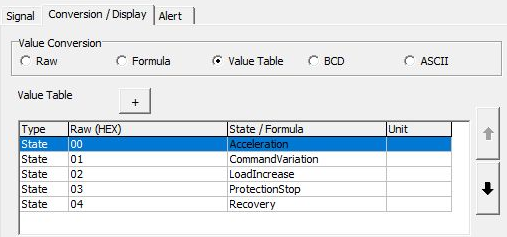
Figure 3. Raw values (hexadecimal) and state names for Fan_Phase_demo.
- Enable the display destination. Under “Display Targets” at the upper right of the same tab, select “Status Monitor” and confirm with “OK.” “Values” is also selected in Figure 4, so the signal appears in the value list as well.

Figure 4. Display destinations for Fan_Phase_demo.
- Check the monitored state name. Make this Set Current, start monitoring, and check the
CH1-1 Fan_Phase_demorow in Status Monitor in Signal Window. Value in Figure 5 isAcceleration, corresponding to Raw value00in Figure 3. StatusDefinedindicates that a state name is defined for the received Raw value.

Figure 5. Received state name for Fan_Phase_demo.
Confirming, Canceling, and Saving
OK confirms this edit. Cancel discards unconfirmed changes in this editing dialog. It does not undo other edits already confirmed in the Catalog. To save to a file, use Save in the Catalog.