Defining Derived Signals
Overview
A derived signal is a result calculated from signals registered in the Catalog. It differs from a bus signal, which directly extracts specific bits from the bus. You can create numeric conversions, comparisons, and combinations of multiple conditions.
Creation Procedure
- Stop monitoring and select the Set to use in Signal Catalog. Check the input signal's Protocol, ID, and channel, not just its name. Figure 1a selects
Target_RPM_demo, CAN FD, ID310, CH1-1. - Click “+ Derived.”
- Enter Signal name.
- Find the input signal under Signals on the right of the Formula tab, then double-click it to insert it into the formula. In Figure 1b, select
Target_RPM_demo | CAN FD+BRS | CatalogId 1. Also check the frame type and CatalogId to avoid confusing it with a LIN signal of the same name. Add operators or Functions as needed.

Figure 1a. Checking the input signal ID/channel before creating a derived signal.
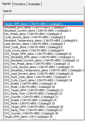
Figure 1b. Selecting an input signal from Signals to insert into the formula.
- Check Detected result and the validation results at the bottom of the screen. For numeric results, configure Unit and Decimal places.
- Check input signals, dependencies, and channel assignments in Inputs and Details.
- Configure Display settings and Alert as needed, then confirm with OK.
- Check membership, Current Set, and display destinations in the Catalog, then save with Save.
Screen Reference
The example shows derived signal Target_RPS using Target_RPM_demo on CH1 as input. It divides SIG(1), assigned to that input, by 60 and uses unit r/s. For example, an input of 1800 rpm produces 30 r/s.
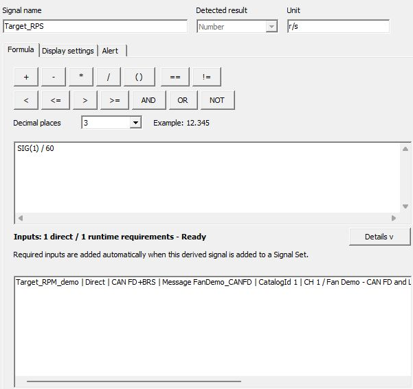
Figure 2. Converting rotational speed to r/s using SIG(1) / 60.
| Item | Description |
|---|---|
| Signal name | Name of the derived signal. |
| Detected result | Result type inferred from the formula, such as Number or Boolean. |
| Unit | Display unit for numeric results. The unit name alone does not convert values. |
| Formula | Build a formula using input signals, operators, constants, and functions. |
| Decimal places | Number of decimal places displayed. Check the format under Example. |
| Signals / Search | Find and select input candidates to insert into the formula. |
| Functions | Insert functions such as ABS, MIN, MAX, and IF into the formula. |
| Examples | View formula examples. |
| Inputs / Details | Check required inputs, dependencies, and availability. |
| Display settings | Configure destinations such as the value list and graphs. |
| Alert | Configure alert conditions for the derived result. |
| OK / Cancel | Confirm this edit or discard unconfirmed changes. |
Formula Examples
Signal references inserted from Signals have the form “SIG(number).” The number is an identifier in the Catalog. Do not enter the example numbers unchanged; insert the actual signal you use from the list.
| Purpose | Example formula | Result |
|---|---|---|
| Convert speed from km/h to m/s | SIG(number) / 3.6 | Input 36 km/h gives 10. Set Unit to m/s. |
| Test whether a value reaches an upper limit | SIG(number) >= 10 | Produces a Boolean result. |
| Absolute value | ABS(SIG(number)) | Absolute value of a number. |
| Smaller of two signals | MIN(SIG(number1), SIG(number2)) | Numeric comparison. |
| Select a number by condition | IF(SIG(number) >= 10, 1, 0) | 1 if the condition is true, otherwise 0. |
Use AND/OR/NOT for Boolean conditions. The IF condition must be Boolean, and its true/false values must have the same type. You can also insert comparison symbols and parentheses using the on-screen buttons.
Input Signals and Sets
Adding a derived signal to a Set also brings its required input signals under management. Do not estimate limits using only the number of derived signals; count required input signals too.
Input bus signals require definitions matching the target frames and channel assignments. Do not treat the result as a normal number if an input has not been received, is unassigned, cannot be referenced, or is otherwise unavailable to the formula. Check validation messages and correct circular references or type mismatches.
If the input channel cannot be verified during automatic restoration of a saved Current Set, derived signals depending on that input also remain pending. Reconnect the target device and use “Device” → “Refresh” to recheck assignments.
When using multiple signals, inputs may update at different frame intervals. Check not only the calculated result but also the input update states and source frames.
Checking Edited Results
Check the input and derived signals in Current Set and compare results against manual calculations using known input values. Recheck Signals references and Inputs after renaming a signal or replacing source definitions.
Displaying both the input and derived signals in Values with the Time/Value format lets you check values and update times together. Figure 3 shows analysis of a recorded real log in Signal Analysis.
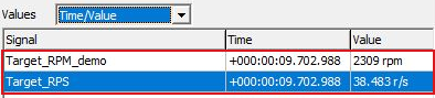
Figure 3. Comparing input and derived rotational speeds at the same timestamp.
Time is +000:00:09.702.988 for both rows. Input Target_RPM_demo is 2309 rpm and derived signal Target_RPS is 38.483 r/s, matching 2309 ÷ 60 from the formula in Figure 2 displayed to three decimal places.
Save the configuration to MPXSIG, including derived signals.
Example: Converting the Sample Speed Signal
- Add Speed from the sample DBC to the Set and assign the receiving channel.
- Use + Derived, name the signal “Speed_mps,” insert Speed from Signals, and append
/ 3.6. - Set Unit to m/s, check Inputs and display destinations, and confirm with OK.
- Check that an input Speed of 36 km/h in Current Set produces 10 m/s. This is a calculation example; actual received values depend on the input.
Derived values can be used for monitoring and analysis, but are distinct from values set directly in transmission frame bits and from Signal Trigger targets. Derived signals cannot be selected for Signal Trigger.