Importing Communication Definition Files
Overview
Import signal and frame definitions from a DBC into Signal Catalog. To use them for monitoring, add the required signals to a Signal Set and configure channels and display destinations. For analysis, proceed to selecting analysis definitions; for transmission, proceed to applying definitions to transmission settings. Signals used only for transmission do not need to belong to a monitoring Set.
Importing a file, adding signals to a Set, and configuring device communication are separate operations. Loading communication definitions does not mean that communication settings in Device Window or transmission operations are automatically ready.
Import Procedure
- Stop monitoring and open Signal Catalog from the main toolbar.
- Click Import and select a DBC file. You can use the sample DBC for this example.
- In Import Communication Definitions, check the character encoding, signal/frame counts, and warnings.
- Select the required items in Signals. Expand nodes and frames to check signal names and bit positions.
- In Frames, check frame names, standard/extended IDs, communication types, and data lengths. Frames in the DBC are automatically registered regardless of selections in Signals.
- Click Import.
- Check the imported signals and frames under Signals and Frames in the Catalog.
Apply imported definitions according to their intended use.
- For monitoring, turn on In Set for the target signals in Signals, configure channels and display destinations, and make the Set Current. Save as described in the first-time monitoring procedure.
- For analysis, select the definitions and Set to use for analysis.
- For transmission, select the frames to use in Frames from Catalog.
If no definition file is available, you can register the required signals manually.
Import Screen Reference
Opening the sample signal-example.dbc displays Speed and State under SensorNode → SensorFrame. Both signals are selected in the example, with two items to add.
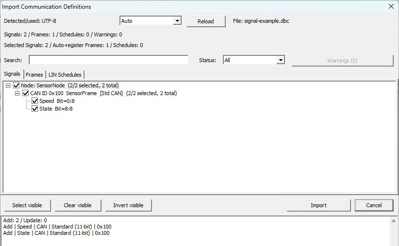
Figure 1. Signals preview before import, with Speed and State selected.
| Item | Description |
|---|---|
| Detected/used | Shows the detected and used character encodings. |
| Encoding selection / Reload | Reloads using automatic detection or the specified encoding. Check this if names are garbled. |
| Signals / Frames / Schedules / Warnings | Shows counts of parsed definitions and warnings. |
| Selected Signals / Auto-register Frames | Shows the number of selected signals, frames to register automatically, and related counts. |
| Search / Status | Filters the display by name or status. Clear the filters if you cannot find an item. |
| Signals | Shows signals in a node/frame hierarchy and lets you select items to import. |
| Frames | Shows frame definitions. |
| LIN Schedules | Shows schedule definitions from an LDF. |
| Select visible / Clear visible / Invert visible | Selects, clears, or inverts selection of visible items. |
| Results / description area at the bottom | Shows candidates for addition/update and descriptions of selected items. |
| Import / Cancel | Executes or cancels this import. |
Read the explanations before using items marked as not importable, unsupported, or carrying warnings. Successfully opening a file does not mean all definitions can be used correctly.
Before confirming the import, open the “Frames” tab to check which frames will be registered automatically.

Figure 2. Frames preview before import, showing the ID, length, and publisher of SensorFrame.
Checks After Importing a DBC
After clicking “Import” and returning to Signal Catalog, check the registered definitions in this order.
- Check the frame in Frames. On the “Frames” tab, select the
SensorFramerow whose Source issignal-example.dbc. In Figure 3, Protocol isCAN, ID / IDE is100(hexadecimal 0x100), Bytes is8, Signals is2, and Publisher isSensorNode.
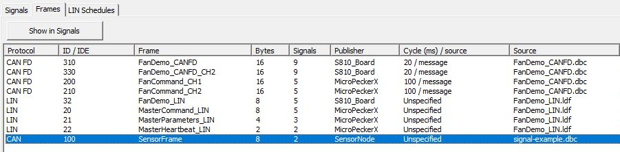
Figure 3. SensorFrame selected in Frames after import.
- Check the two signals and ID format in Signals. With SensorFrame selected, click “Show in Signals” to display
SpeedandStatein Signals. Check that Message isSensorFramefor both. Next, select the Speed row and checkID (Hex): 100,Format: Std., andDL: 8in Signal Definition below. This identifies a frame with standard ID 0x100 and a data length of 8 bytes.
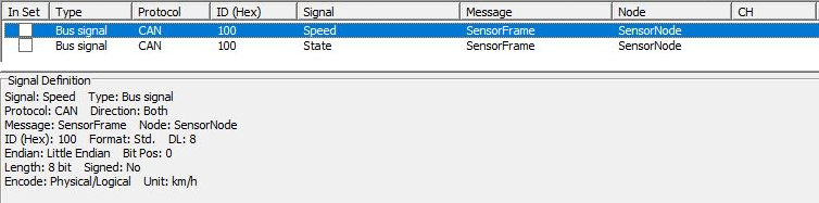
Figure 4. Target rows in Signals (top) and Signal Definition with Speed selected (bottom).
- Compare standard/extended ID, CAN/CAN FD, and data length with the actual frames.
- Check the start bit, length, Endian, and signedness.
- Check Factor, Offset, minimum/maximum, Unit, and state-name mappings.
- For multiplexed signals, check the selector and each branch condition.
The sample DBC defines an 8-byte CAN frame with standard ID 0x100. When using CAN FD, check the communication type and data length in both the target definitions and actual frames.
In the sample, Speed occupies the 8 bits of Byte 0 and State occupies the 8 bits of Byte 1. A Raw value of 100 for Speed converts to 45 km/h. Use Conversion Preview in Signal Setting to compare inputs and results.
Reimporting the Same Definitions
First save the current Catalog to an MPXSIG file with a different name. Reimporting a file from the same location matches definitions from that source and adds new definitions. Files with the same name in different locations are treated as separate sources. Check the signal definitions to add or update under Add/Update in the preview. Check frame contents on each tab and apply them with Import. Frame changes are applied even when Add/Update is 0 because no signal definitions have changed. Manually edited conversions are retained if the source file has not changed. If the source file and manual edits independently change the same definition and conflict, Cannot apply appears and the import cannot be confirmed. Decide which definition to use, resolve the conflict, and reload.
Definitions deleted from the source file are retained for existing references. Deleted frames, and frames whose corresponding signals were deleted or became unsupported, cannot be used to generate new transmission settings. To remove definitions by import source, use Remove Import.
Even if you clear a checkbox in Signals, signal definitions within automatically registered frames may still be added or updated. Check the preview before clicking Import.
Recording the source file name/version, signal count, frame conditions, bit positions, and units helps you review definition changes. Catalog Load replaces the entire Catalog and all Sets, so distinguish it from importing communication definition files.
If Import Errors Appears
“Import Errors” opens if the file cannot be opened or reading fails due to syntax or other errors. Select an item in the error list and check the file name, line number, target, and reported problem. Correct the file location, read permissions, or indicated definitions, then select the file again using Import in the Catalog. If the preview opens but text is garbled, specify the character encoding and use “Reload.”
If Nothing Is Displayed After Import
First check that the target exists in the Catalog, In Set is on, and a channel is assigned. Then compare actual frame conditions and display targets. See Checks When Nothing Is Displayed for details.
For saved-log analysis, result output, and use in transmission settings, see the respective instructions.