Microsoft Excel CAN Simulation Program
Screen Layout (Setting Sheet)
| Item | Description |
|---|---|
| Connect button | Detects MicroPeckerX connected to the PC. |
| Serial | Displays the serial number of the detected MicroPeckerX. |
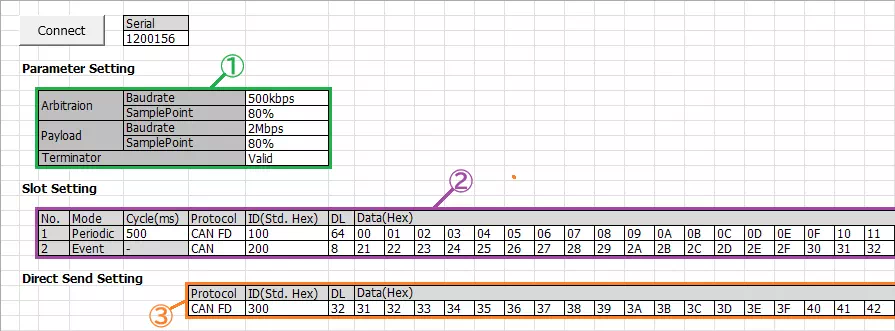
| Parameter Setting (area ①) | Sets baudrate, sample point, and termination resistor enable/disable. |
| Slot Setting (area ②) | Sets periodic preset frame (No.1) and event preset frame (No.2). (*1) |
| Direct Send Setting (area ③) | Sets direct transmit preset frame. (*1) |
*1: Configurable items are as follows.
Transmission cycle (periodic preset frame only), protocol, ID (standard ID only), DL, and data.
Screen Layout (Monitoring Sheet)
| Item | Description |
|---|---|
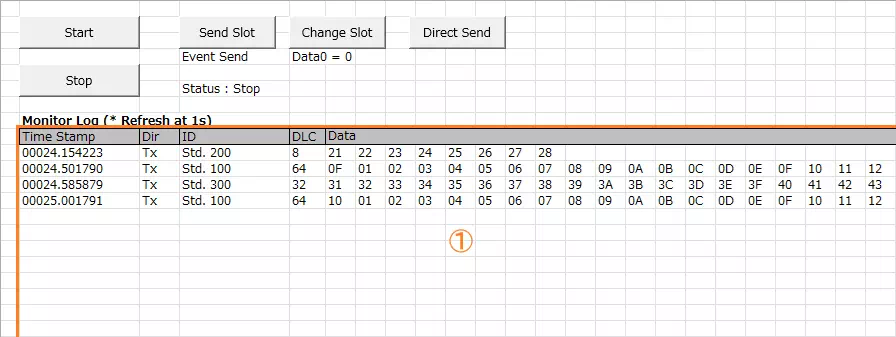
| Start button | Starts monitoring and transmission of periodic preset frames. |
| Stop button | Stops monitoring and transmission of periodic preset frames. |
| Send Slot button | Sends event preset frame. |
| Change Slot button | Changes D1 of periodic preset frame to 00H. |
| Direct Send button | Sends direct transmit preset frame. |
| Monitor Log (area ①) | Displays transmitted/received logs. Logs are updated every second; previous logs are cleared at each update. If no new log exists, no update occurs and previous logs remain displayed. See Monitor Log Details for displayed fields. |
Monitor Log Details
| Item | Description |
|---|---|
| Time Stamp | Displays timestamp in sssss.mmmuuu format. |
| Dir | Displays log direction. Rx: receive log / Tx: transmit log |
| ID | Displays CAN ID and ID format. CAN ID is hexadecimal. ID format is displayed as follows. Std: standard ID / Ext: extended ID |
| DLC | Displays data length (0 to 64). |
| Data | Displays data (D1 to D64) in hexadecimal. |
Preset Frames
The preset frames are as follows.
Transmission cycle, protocol, CAN ID, DL, and Data can be changed on the Setting sheet.
| Frame Type | Slot | Cycle | Protocol | ID | DL | Data (Hex) | ||||||||
|---|---|---|---|---|---|---|---|---|---|---|---|---|---|---|
| Format | CAN ID | D1 | D2 | ... | D8 | ... | D32 | ... | D64 | |||||
| Periodic preset frame (*1) | 1 | 500ms | CAN FD | Standard ID | 100H | 64 | 00 | 01 | ... | 07 | ... | 1F | ... | 3F |
| Event preset frame | 2 | - | CAN | Standard ID | 200H | 8 | 21 | 22 | ... | 28 | ||||
| Direct transmit preset frame | - | - | CAN FD | Standard ID | 300H | 32 | 31 | 32 | ... | 38 | ... | 4F | ||
*1: Only D1 is incremented (+1) for each transmission.
Implementation Example (Source Code with Comments)
The VBA sample application logic is included in MPXCtrl_CANFD_ExcelVBA_Sample.xlsm.
MPXCtrlFree.bas contains API declarations, constants, and structure definitions. The following is an example using the same API sequence as the sample.
Option Explicit

Sub StartCanSimulation()
    Dim dev(0 To 0) As StMPXDeviceInfo
    Dim count As Byte
    Dim ret As Long
    Dim serial As Long
    Dim p As StMPXCANParam

    ' 1) Detect device
    ret = MPXOpen(dev(0), 1, count)
    If ret <> E_OK Or count = 0 Then Exit Sub
    serial = dev(0).Serial

    ' 2) Set CH1 to SIM
    p.Mode = MPX_CAN_MODE_SIM
    p.EnableTerminate = MPX_CAN_TERMINATE_ENABLE
    p.ArbitrationBaudrate = MPX_CAN_PARAM_ABR_500K
    p.ArbitrationSamplepoint = MPX_CAN_PARAM_SP_80P
    p.DataBaudrate = MPX_CAN_PARAM_DBR_2M
    p.DataSamplepoint = MPX_CAN_PARAM_SP_80P
    ret = MPXCANSetParam(serial, 1, p)
    If ret <> E_OK Then Exit Sub

    ' Disable CH2
    p.Mode = MPX_CAN_MODE_NONE
    ret = MPXCANSetParam(serial, 2, p)
    If ret <> E_OK Then Exit Sub

    ' 3) Set log acquisition mode to API mode
    ret = MPXSetGetLogMode(serial, 1, MPX_GETLOGMODE_GETLOGAPI)
    If ret <> E_OK Then Exit Sub

    ' 4) Start monitoring
    ret = MPXMonitorStart(serial, MPX_SYNC_MASTER)
End Sub

Sub StopCanSimulation(ByVal serial As Long)
    ' 5) Stop and exit
    Dim ms As Long, us As Integer
    Call MPXMonitorStop(serial, ms, us)
    Call MPXClose
End Sub