Microsoft Visual C# CAN Simulation Program
Screen Layout
| Item | Description |
|---|---|
| Connect button | Detects MicroPeckerX connected to the PC. |
| Serial | Displays the detected MicroPeckerX serial number. |
| Start button | Starts monitoring and transmission of periodic preset frames. |
| Stop button | Stops monitoring and transmission of periodic preset frames. |
| Status | Displays monitoring and periodic preset transmission status. Start: running / Stop: stopped |
| Send Slot button | Sends the event preset frame. |
| Change Data button | Changes D1 of the periodic preset frame to 00H. |
| Send Direct button | Sends the direct transmit preset frame. |
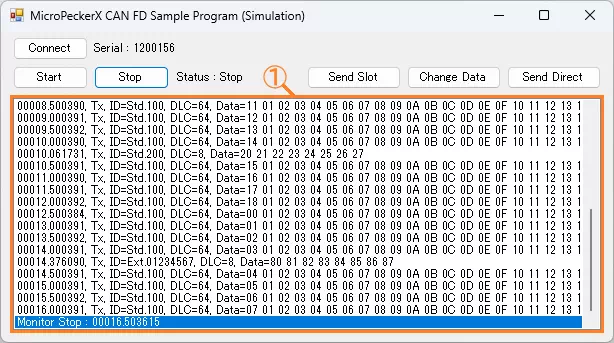
| Log display area (area ①) | Displays transmitted/received log information. In this sample, up to 1024 logs are acquired per single log acquisition API call. No upper limit is implemented for retained display rows. For long continuous operation, add row limit and old-row deletion logic in the application. For display content, see Log Display Details. |
Log Display Details
Display content is as follows. Items are comma-separated.
| # | Item | Description |
|---|---|---|
| 1 | (No item name) | Displays timestamp in sssss.mmmuuu format. |
| 2 | (No item name) | Displays log direction. Rx: receive log / Tx: transmit log |
| 3 | ID | Displays CAN ID and ID format. CAN ID is shown in hexadecimal. ID format is shown as follows. Std: standard ID / Ext: extended ID |
| 4 | DLC | Displays data length (0 to 64). |
| 5 | Data | Displays data (D1 to D64) in hexadecimal. Bytes are separated by spaces. |
Preset Frames
Details of each preset frame are shown below.
| Frame Type | Slot | Protocol | ID | DL | Data (Hex) | ||||||
|---|---|---|---|---|---|---|---|---|---|---|---|
| Format | CAN ID | D1 | D2 | ... | D8 | ... | D64 | ||||
| Periodic preset frame (*1) | 1 | CAN FD | Standard ID | 100H | 64 | 00 | 01 | ... | 07 | ... | 3F |
| Event preset frame | 2 | CAN | Standard ID | 200H | 8 | 20 | 21 | ... | 27 | ||
| Direct transmit preset frame | - | CAN FD | Extended ID | 01234567H | 8 | 80 | 81 | ... | 87 | ||
*1: Only D1 is incremented (+1) on each transmission.
Implementation Example (Source Code with Comments)
Source: MPXCtrl_CANFD_CSharp_Sample/MPXCtrl_CANFD_CSharp_Sample/Form1.cs
// Explicitly initialize including array members at startup
private void Form1_Load(object sender, EventArgs e)
{
    Slots = new StMPXCANSlot[28];
    for (int i = 0; i < 28; i++)
    {
        Slots[i].Increment = new byte[64];
        Slots[i].Frame.Data = new byte[64];
    }

    Logs = new StMPXCANLog[1024];
    for (int i = 0; i < 1024; i++) Logs[i].Data = new byte[64];
}

private void StartButton_Click(object sender, EventArgs e)
{
    // 1) Detect device
    var info = new StMPXDeviceInfo[1];
    byte count = 0;
    int ret = MPXCtrl.Open(ref info, 1, ref count);
    if (ret != MPXConst.E_OK || count == 0) return;
    Serial = info[0].Serial;

    // 2) Configure CAN parameters (CH1=SIM, CH2=NONE)
    var param = new StMPXCANParam();
    param.Mode = MPXConst.MPX_CAN_MODE_SIM;
    param.EnableTerminate = MPXConst.MPX_CAN_TERMINATE_ENABLE;
    param.ArbitrationBaudrate = MPXConst.MPX_CAN_PARAM_ABR_500K;
    param.ArbitrationSamplepoint = MPXConst.MPX_CAN_PARAM_SP_80P;
    param.DataBaudrate = MPXConst.MPX_CAN_PARAM_DBR_2M;
    param.DataSamplepoint = MPXConst.MPX_CAN_PARAM_SP_80P;
    ret = MPXCtrl.CANSetParam(Serial, 1, ref param);
    if (ret != MPXConst.E_OK) return;
    param.Mode = MPXConst.MPX_CAN_MODE_NONE;
    ret = MPXCtrl.CANSetParam(Serial, 2, ref param);
    if (ret != MPXConst.E_OK) return;

    // 3) Set log acquisition method
    ret = MPXCtrl.SetGetLogMode(Serial, 1, MPXConst.MPX_GETLOGMODE_GETLOGAPI);
    if (ret != MPXConst.E_OK) return;

    // 4) Register slots, then start monitoring
    ret = MPXCtrl.CANSetSlot(Serial, 1, Slots, 2);
    if (ret != MPXConst.E_OK) return;
    ret = MPXCtrl.MonitorStart(Serial, MPXConst.MPX_SYNC_MASTER);
}

private void timer1_Tick(object sender, EventArgs e)
{
    // 5) Periodically fetch logs and show on UI
    ushort count = 0, num = 1024;
    byte over = 0;
    int ret = MPXCtrl.CANGetLogEx(Serial, 1, ref Logs, num, ref count, ref over);
    if (ret != MPXConst.E_OK) timer1.Enabled = false;
}