MicroPeckerX CAN FD Analyzer
Frequently Asked Questions for MicroPeckerX CAN FD Analyzer.
Product Specifications
What is included in the product package?
The
- MicroPeckerX unit
- USB (microB) cable
- Synchronization cable
- GUI software for CAN/CAN-FD analyzer
CAN cables are sold separately:
{S810-MX-FD2} package includes:- MicroPeckerX unit
- USB (microB) cable
- Synchronization cable
- GUI software for CAN/CAN-FD analyzer
CAN cables are sold separately:
CAN 1ch Clip Cable {S810-MX-CB1} and CAN 2ch D-sub Cable {S810-MX-CB2}.The product asks me to enter CAN standard/extended IDs as 29-bit values. Is this proprietary?
You can choose two CAN ID display/setting formats in
-
-
Both notations are supported.
Option -> CAN/CAN-FD ID Form:-
ALL ID: standard ID (11-bit) + extended ID (18-bit) as a continuous 29-bit value (default).-
SID/EID: standard and extended IDs shown separately.Both notations are supported.
What happens when bus-off occurs?
When bus-off occurs, the error is cleared immediately without a recovery sequence, and communication resumes in normal state.
Can I set recessive and dominant waveform widths independently?
No. Under CAN standard (ISO 11898), recessive and dominant waveform widths cannot be set differently.
Does it support J1939?
This product is an analyzer for CAN physical/data-link layers. Dedicated J1939 automatic decode display is not included, but physical-layer monitoring and simulation are possible. Configure J1939 data structure (bit position/length, etc.) on user side.
Does it support CANopen?
It supports CAN physical/data-link layer monitoring and simulation. However, CANopen-specific auto-display features are not included. Bit position/length and related settings must be configured by the user.
Can Vector DBC files be loaded?
DBC files are not supported.
Can I perform CAN conformance tests?
No. CAN conformance test features are not supported. Analog waveform analysis is also not included; main functions are digital communication monitoring/analysis (data and error states).
Transmission stops when I close my laptop lid during CAN frame transmission. Can communication be maintained?
This is usually caused by power-saving settings. Closing the lid may put the PC into sleep/hibernate and stop communication.
To keep communication active, update your PC settings (Windows 11 example):
1. Open
2. Under
To keep communication active, update your PC settings (Windows 11 example):
1. Open
Settings -> System -> Power & battery -> Lid, power & sleep button controls.2. Under
Plugged in, set When I close the lid to Do nothing.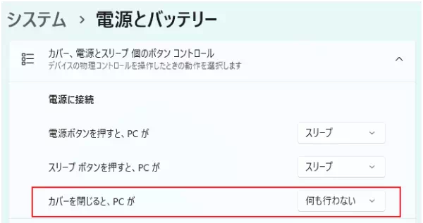
Can it synchronize time with MicroPecker? If so, can both datasets be shown on the same graph?
Time synchronization with MicroPecker is possible. However, because GUI applications are different, both datasets cannot be displayed on the same graph. Timestamp values in each output log file are synchronized.
If the device is taken out or lost, is there a risk of information leakage (Tx/Rx logs, etc.)?
Security concern is minimal for these reasons:
- The unit itself does not store Tx/Rx data (data is saved as files on PC).
- Temporary data such as communication settings is cleared when power is turned off.
Therefore, even if the device is lost, data leakage from the device body is unlikely.
- The unit itself does not store Tx/Rx data (data is saved as files on PC).
- Temporary data such as communication settings is cleared when power is turned off.
Therefore, even if the device is lost, data leakage from the device body is unlikely.
Application
Can this product use monitor/simulation functions? Is additional software purchase required?
Yes. This product supports CAN/CAN-FD monitoring and communication-node simulation. The required application is bundled; no additional application purchase is required.
Can bundled application software be controlled from user software?
No. Bundled application software cannot be operated directly from user software. If you need control via user software, use the application development library and develop a dedicated application.
Can script languages be used in simulation?
Script languages are not supported. To control CAN/CAN-FD communication, use the API set provided as
MicroPeckerX CAN-FD Application Development Library and build your own application.Even when enlarging the app window, some buttons are clipped. Is this a bug?
This is not a bug. It occurs when Windows display scaling is changed via
Custom scaling. It does not occur when scaling is selected from the standard drop-down list. Since Windows also does not recommend custom scaling, use the standard scaling selection.Monitoring Function
In
Each ID Window, can text color change when data for an ID changes?Yes. By setting
Label Filter Window, text/background color can be changed when Tx/Rx frames meet specific conditions. This applies to Each ID Window, Monitor Window, and Analyze Window.Can high-speed frames such as 200 μs cycle be received without drops?
Yes. Depending on bitrate and burst conditions, PC performance can affect results. Please contact us for detailed confirmation.
Can I monitor two channels simultaneously with different communication speeds?
Yes. Communication baud rate can be set per channel in
Device Window.After starting monitoring for CAN FD communication, communication fails and
Stuff Error is shown in Monitor Window.The peer device may be using
Non-ISO CAN FD. If so, change the peer device setting to use ISO CAN FD protocol.Can MicroPeckerX communicate directly with a target device?
Yes. Because this product can return ACK, simply connecting to the target allows CAN reception monitoring. It can also transmit frames, including up to 28 preconfigured frames, arbitrary ID/data transmission during operation, and replay-based transmission from previously captured logs.
Can error frames be detected or generated?
Detection of errors such as ACK error and overload frame error is possible. However, generating error frames is not supported.
Monitor Synchronization error. appears when monitoring starts.Confirm synchronization cable is connected correctly. If error persists, device failure is possible; contact Sunny Giken.
While monitoring, trying to view older data in
Monitor Window always jumps back to latest data. Is this expected?Yes. During monitoring,
Monitor Window is designed to show latest information each refresh cycle.In log files, normal CAN-FD frame
Type is shown as -. Is this okay?Yes. CAN-FD protocol has no remote frame, so
Type is shown as -.Logging was enabled and Monitor Window showed frames, but on stop I got
There are no logging data. Why?This occurs when
Triggered is selected in Trigger Window and Start Log Trigger is enabled. If no frame matches Start Log Trigger, file logging does not start. Use Free Run to avoid this.Is there a maximum number of files when saving split logs?
The limit depends on destination drive capacity; there is no fixed file-count limit. Split logs use 3-digit suffixes initially, and continue with 4 digits (
1000, etc.) after 999.Can I save only specific IDs to log files, and save per-ID files separately?
By design, all IDs are logged for data integrity. However, you can create ID-specific logs from the output file:
(1) Open
(2) Load the log file.
(3) Open
(4) Check target IDs in
(5) Select
(6) Save from Analyze Window.
(7) Repeat (4)-(6) for other IDs to create separate files per ID.
(1) Open
Analyze Window and select Analyze tab.(2) Load the log file.
(3) Open
Filtering tab and click Get ID List to enable ID filtering.(4) Check target IDs in
ID Filtering Setting.(5) Select
ID Filtering and click Execute to show only selected IDs.(6) Save from Analyze Window.
(7) Repeat (4)-(6) for other IDs to create separate files per ID.
Simulation Function
Can Simulation Window transmit while incrementing IDs, or transmit in file order?
Yes. Using log replay, you can load this product's logging-file format and transmit in file order. With Log Editor, you can create/edit replay files and define arbitrary transmission order.
If the same Log Trigger is set to frame 1 and frame 3, both are sent when frame 1 trigger is met. Can this be avoided?
With this product, if multiple frames share the same log trigger condition in Simulation Window, all frames with that condition are transmitted simultaneously when triggered. So avoiding this behavior is difficult.
Can one device replay different log files on two channels simultaneously?
No. For one unit, log replay can be used on only one channel. Even though settings may be configured for both channels, monitoring cannot start and a message indicates 2-channel simultaneous log replay is not possible.
When using
Log Replay in Simulation Window, Arb. Lost occurs and CAN frame transmission fails. What should I do?This can occur if there is no termination resistor on the CAN bus. Check
Terminator Enabled under Other Setting in Device Window. Enabling termination may resolve transmission failure.Can specific frames/data be sent cyclically, and can values be changed during transmission?
Yes. In slot-transmission mode of CAN simulation, specific ID/data can be sent periodically. Transmission data can also be changed.
Simulation allows up to 28 configured frames. How can I transmit more than that?
Max 28 frames means the slot count limit in slot-transmission mode. You can still manually transmit arbitrary frames at any timing in addition to slot frames. You can also use Log Replay and Burst Transfer modes for larger transmission scenarios.Can I send signal B 10 ms after receiving signal A?
Yes. Using simulation control, you can implement behavior like
send signal B 10 ms after receiving signal A. Set signal B frame to Event Send, choose Receive Trigger or Log Trigger, and set delay to 10 ms.Can transmit-frame data be changed automatically?
Yes. Using simulation, transmit data can be auto-incremented (+1). In Simulation Window frame settings, use
Increment Setting to enable per-byte auto change. For more complex behavior, custom development using the application development library is required.Can transmit-frame settings be saved/reused via setting files?
Yes. The application supports saving/loading settings files, and saved settings can be used on another PC.
When peer does not return ACK, logs continuously show ACK errors with
(1) Is this retransmission after ACK error?
(2) Why is
Dir=R (receive).(1) Is this retransmission after ACK error?
(2) Why is
Dir shown as R?Yes, the following approaches are possible depending on purpose/configuration:
• Connect one MicroPeckerX channel per CAN bus for one-to-one ECU communication.
• Use different IDs per ECU for frame Tx/Rx separation.
• Reproduce data sent by multiple ECUs using log replay.
Please consult us for the best configuration.
• Connect one MicroPeckerX channel per CAN bus for one-to-one ECU communication.
• Use different IDs per ECU for frame Tx/Rx separation.
• Reproduce data sent by multiple ECUs using log replay.
Please consult us for the best configuration.
Hardware
What is the maximum rated voltage applicable to CANHi/CANLo terminals?
The maximum rated applicable voltage is approximately
5V-5.5V.What is the CAN-bus side connector specification of CAN cables?
It depends on cable type:
• CAN 1ch Clip Cable: independent clips for CAN-Hi, CAN-Lo, and GND.
• CAN 2ch D-sub Cable: D-sub (9-pin).
For other connector types, conversion is required on customer side. You can also connect
• CAN 1ch Clip Cable: independent clips for CAN-Hi, CAN-Lo, and GND.
• CAN 2ch D-sub Cable: D-sub (9-pin).
For other connector types, conversion is required on customer side. You can also connect
CAN 1ch Clip Cable to the CAN-bus side connector of CAN 2ch Dsub Cable to convert D-sub (9-pin) to clips.